E2600 Controller-Drive Tray Installation Guide 15
7. Host Interface Card Link 5 Up LED
8. Host Interface Card Link 5 Active LED
9. iSCSI Host Interface Card Connector 5
10. Host Interface Card Link 6 Up LED
11. Host Interface Card Link 6 Active LED
12. iSCSI Host Interface Card Connector 6
13. ESM Expansion Fault LED
14. ESM Expansion Active LED
15. Expansion SFF-8088 Port Connector
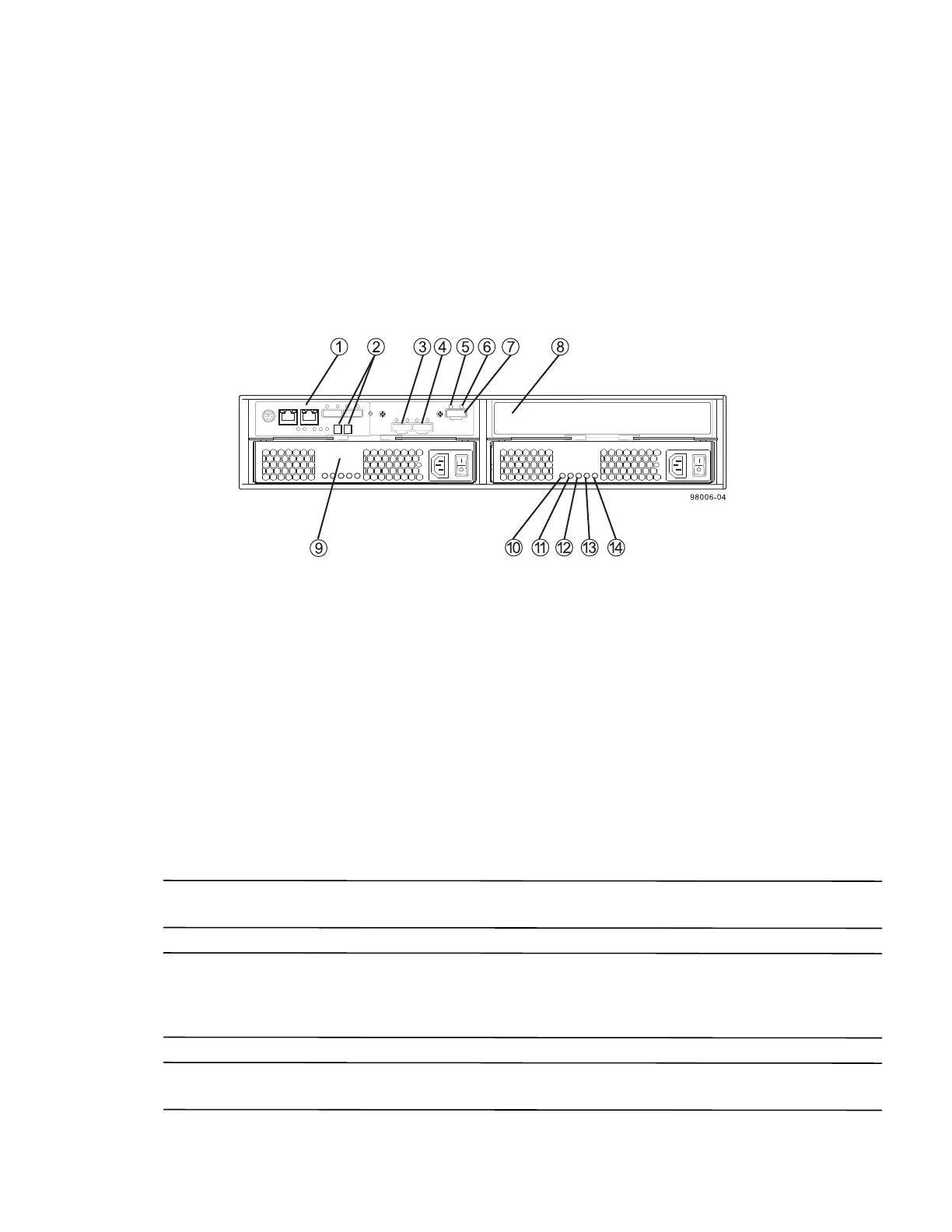
Figure 12 E2612 or E2624 Controller-Drive Tray Simplex Configuration – Rear View
1. Controller A Canister
2. Seven-Segment Display
3. Host Interface Card Connector 1
4. Host Interface Card Connector 2
5. ESM Expansion Fault LED
6. ESM Expansion Active LED
7. Expansion Port SFF-8088 Connector
8. Controller Air Blocker
9. Power-Fan A Canister (optional)
10. Standby Power LED
11. Power-Fan DC Power LED
12. Power-Fan Service Action Allowed LED
13. Power-Fan Service Action Required LED
14. Power-Fan AC Power LED
ATTENTION Possible equipment damage – You must use the supported drives in the drive tray to ensure proper
performance. For information about supported drives, contact a Technical Support representative.
ATTENTION Risk of equipment malfunction – To avoid exceeding the functional and environmental limits,
install only drives that have been provided or approved by the original manufacturer. Not all controller-drive trays
are shipped with pre-populated drives. System integrators, resellers, system administrators, or users of the
controller-drive tray can install the drives.
NOTE In a simplex configuration, the Controller Air Blocker must be kept in place to ensure proper air flow to the
components within the canister.