E2600 Controller-Drive Tray Installation Guide 17
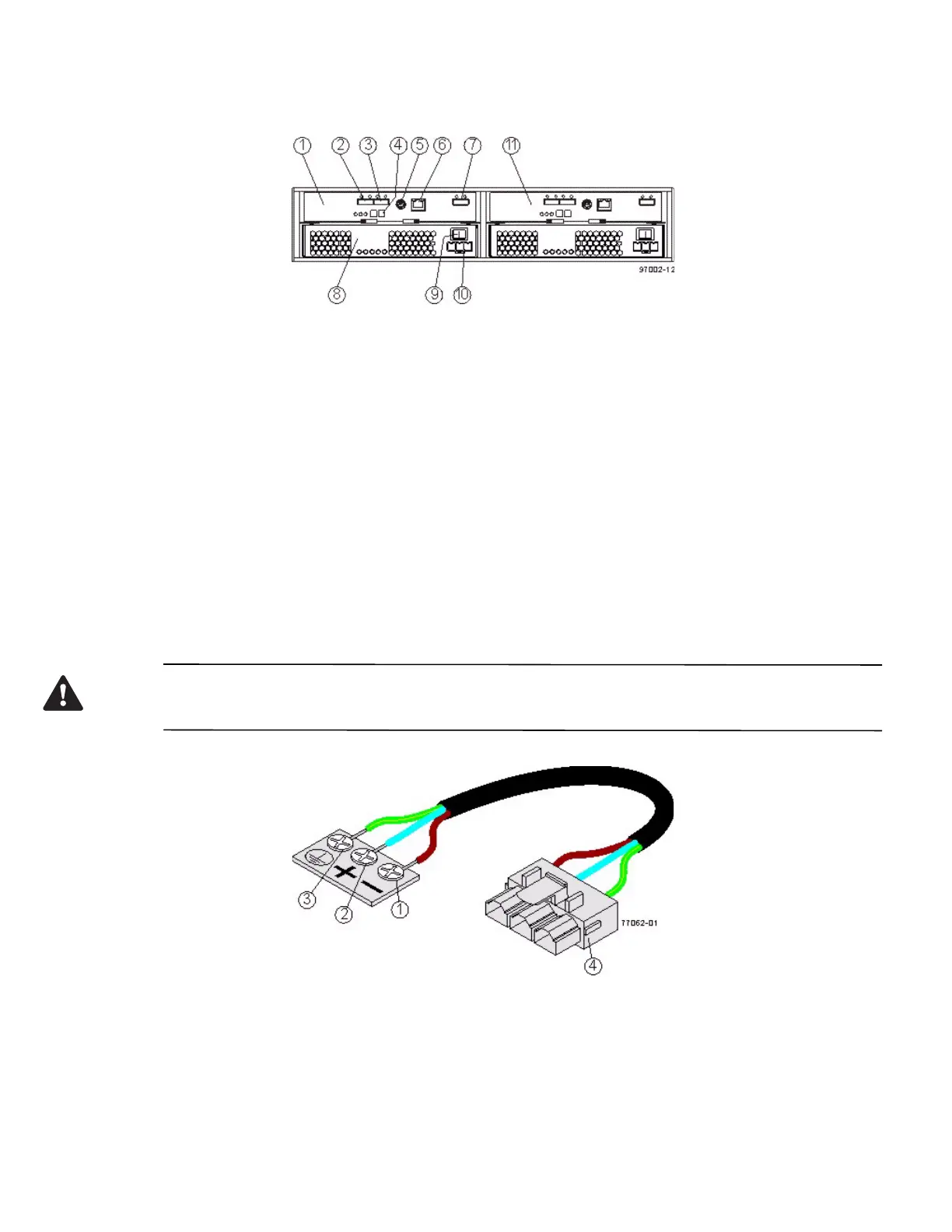
Figure 16 DE1600 Drive Tray or DE5600 Drive Tray with DC Power Option – Rear View
1. ESM A Canister
2. Host Connector 1
3. Host Connector 2
4. Seven-Segment Display Indicators
5. Serial Connector
6. Ethernet Connector
7. Expansion Port SFF-8088 Connector
8. Power-Fan Canister
9. Power Connector
10. Power Switch
11. ESM B Canister
You can order an optional DC power supply connection and connector cables for the drive tray. A qualified service
person is required to make the DC power connection per NEC and CEC guidelines. A two-pole 30-amp
circuit breaker is required between the DC power source and the drive tray for over-current and short-circuit
protection. Before turning off any power switches on a DC-powered drive tray, you must disconnect the two-pole
30-amp circuit breaker.
WARNING (W12) Risk of electrical shock – This unit has more than one power source. To remove all power from
the unit, all DC MAINS must be disconnected by removing all power conn
ectors (item 4 below) from the power
supplies.
1. Supply (Negative), Brown Wire, -48 VDC
2. Return (Positive), Blue Wire
3. Ground, Green/Yellow Wire
4. DC Power Connector