86 E2600 Controller-Drive Tray Installation Guide
2. If there is a black, plastic plug in the SAS expansion connector of the controller, remove it.
3. Insert one end of the cable into the SAS expansion connector on the controller in slot A in the controller-drive
tray.
4. Insert the other end of the cable into the connector with an up arrow on the ESM in slot A in the drive tray.
5. Are you adding more drive trays?
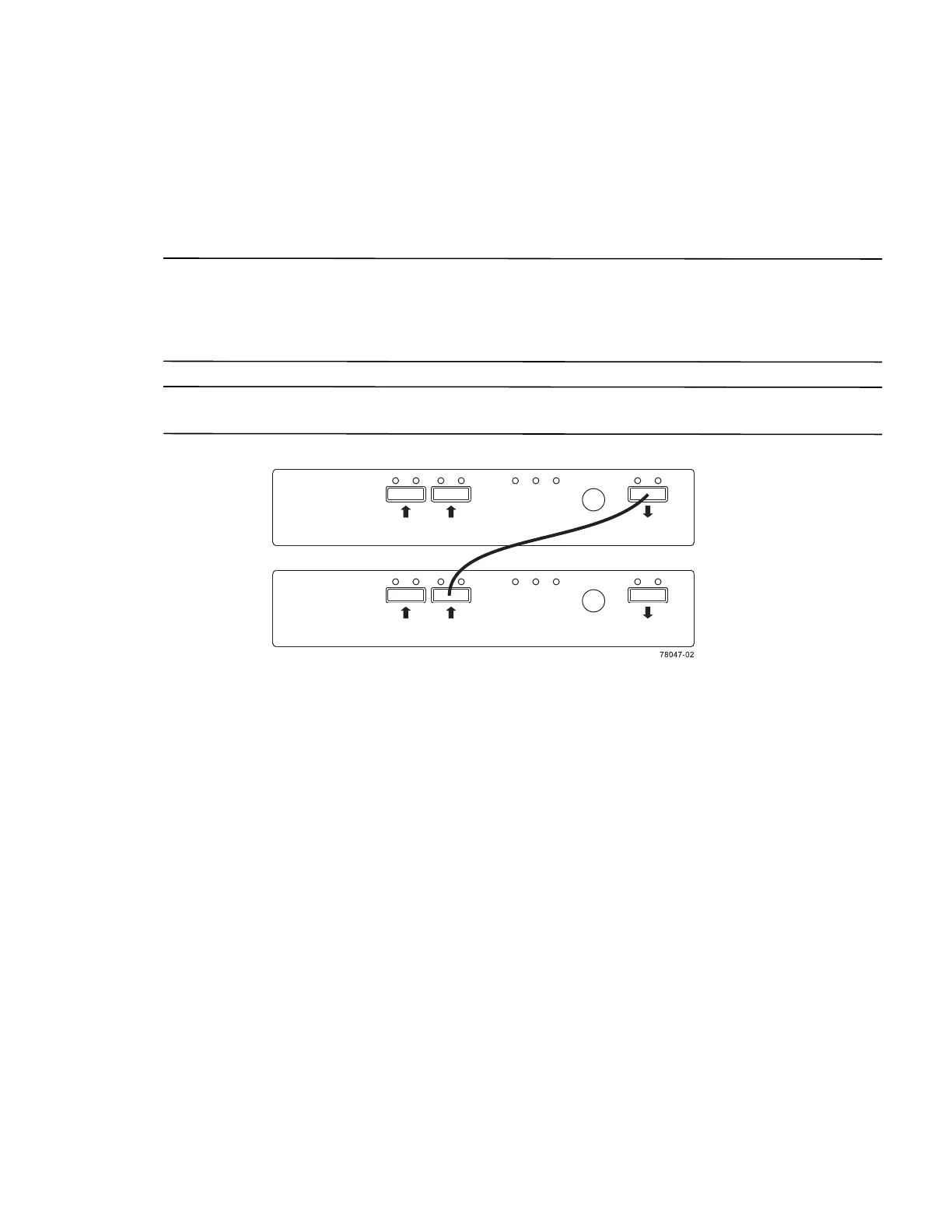
NOTE Each ESM in a drive tray has three expansion connectors: two on the left-center of the ESM and one in the
upper-right side. When connecting from an ESM in one drive tray to an ESM in another drive tray, make sure that
you connect the connector on the upper-right to one of the connectors on the left-center. The following figure shows
these arrows on an ESM. If the cable is connected either between the two left-center ESM connectors or between
two upper-right ESM connectors, communication between the two drive trays is lost.
NOTE It does not matter which of the two left-center ESM connectors you use to connect to the expansion
connector on the far-right side.
Figure 83 Connecting a Cable from One ESM to a Second ESM
— Yes – Go to step 6.
— No – Go to step 9.
6. In the ESM in the first drive tray, insert one end of the cable into the connector
on the far-right side.
7. In the ESM in the next drive tray, insert the other end of the cable into one of the connectors in the left-center
of the ESM.
8. Repeat step 6 through step 7 for each drive tray that you intend to add to the storage array.
9. To each end of the cables, attach a label with this information:
— The controller ID (for example, controller A)
— The ESM ID (for example, ESM A)
— The ESM connector (In or Out)
— The drive tray ID