13 DISMANTLING AND ASSEMBLY
OF SPECIAL UNITS
PAGE
13.6R
3 Safety Precautions
For the installation of the STP-2A as well as for the separate mini transformer the
latest regulations which apply for electrical installations must be adhered to.
CAUTION
If a temperature sensor is operated within the ex–area there must be a safeguard
barrier installed between the temperature controller and the temperature sensor.
Please see Page 13.12 for the switching diagram.
When switching of inductive loads (contactors) we recommend the wiring in of spark
blow-out coils.
4 Installation of Temperature Sensor and Controller
4.1 Reversable Stators, Pump Typ N-Ipos
®
M.Champ
®
When reversing the stator pls. mount the temperature sensor at the 2nd bore and
shut the 1st bore by the closing cap.
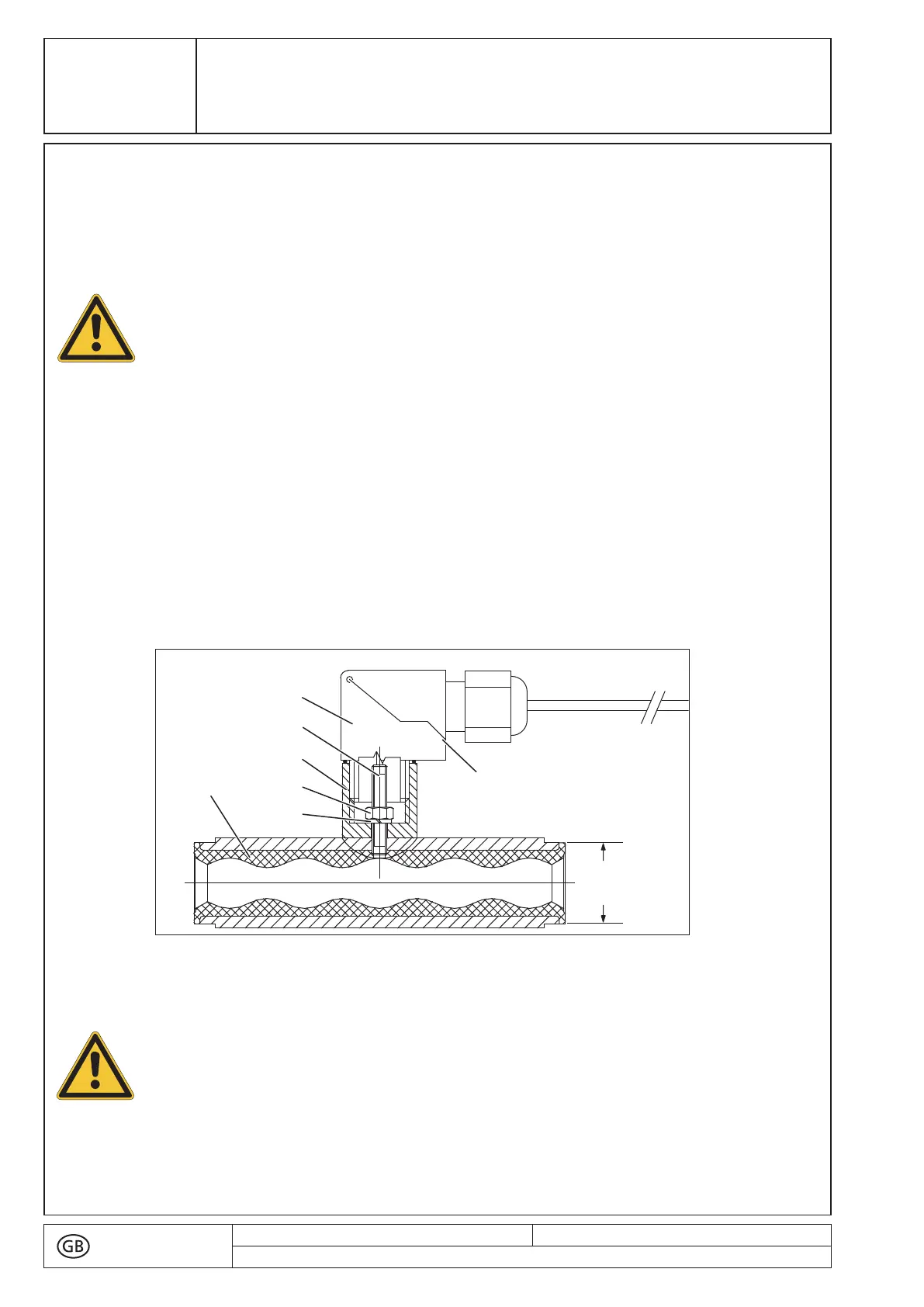
4.2 Small Stators with Diameter (Ø) d = 27 mm
The stators (3005) are delivered with a built-in temperature sensor (4180).
Fig. 1: Installation in d = 27 mm diameter stators
■ Slip spacer piece (0150) onto sensor (4180). Tighten down hex nut (4465) with spring
washer (4130) to stator (3005).
(pls. slip these parts from behindover the cable and screw on to the sensor).
text no.
R 13105-2/8
issued: 14.10.2019
Revision: 23
copy to:
¬D
!
CAUTION
Secure the distance piece (0150) against rotating using a suitable tool when
assembling and disassembling the snap elbow (4710).
86
 Loading...