13 DISMANTLING AND ASSEMBLY
OF SPECIAL UNITS
PAGE
13.10
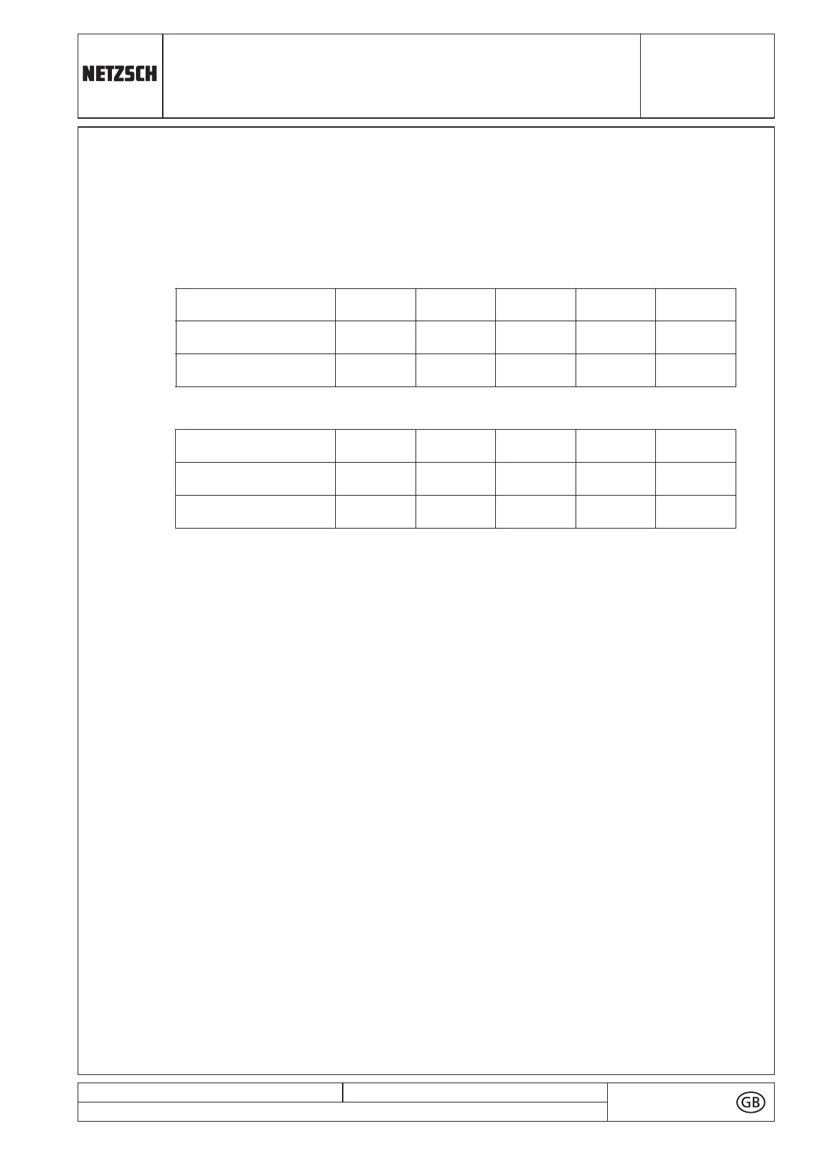
4.6 Wire resistance and indication error
● The wire resistance and the resistance of the temperature sensor PT100 combine
together and thus result in an indication error at the STP-2A temperature controller
with a connection for a 2-wire-PT100.
Indication error per meter of wire length for various cross sections:
conductors acc. to US dimension indication:
● This indication error does not affect the function of the temperature controller.
● With long measuring wires it is however necessary to choose a sufficiently large wire
cross section to reduce the indication error as much as possible.
● It is possible to correct the indication up to +/- 10 °K.
For this aim the normally not accessible parameters have to be changed.
For more information please contact our service department.
ATTENTION! If a safeguard barrier is used, the indication error is compensated
automatically (see chapter 10.10).
5 Set Point Parameters
There are options to adjust the controller by setting various parameters. This is done
on three levels.
The first level gives access to the set points (cut-off temperatures). Two independent
set points can be fed in. The selection of the set point is done by the switching input
E1.
On the second and third level all the remaining control parameters can be set or
adjusted. These parameters, however, have been preset in the factory and the entry
to this level is intentionally made difficult in order to avoid accidental or non–
authorized adjustment of these values.
Important:
Any changes by the customer of the values preset in the factory are not permitted as
this may result in dangerous functional errors.
issued: 14.10.2019
Revision: 23
text no.
13105-6/8
copy to:
wire [mm
2
]
2x0,34
2x0,50
2x0,75
2x1,0
2x1,5
wire resistance [Ω/m]
0,11
0,08
0,05
0,04
0,027
indication error + [°C]
0,29
0,20
0,13
0,10
0,07
wire [mm
2
]
AWG22
AWG20
AWG18
AWG16
AWG14
wire resistance [Ω/m]
0,11
0,08
0,05
0,04
0,027
indication error + [°C]
0,29
0,18
0,13
0,08
0,05
93
 Loading...