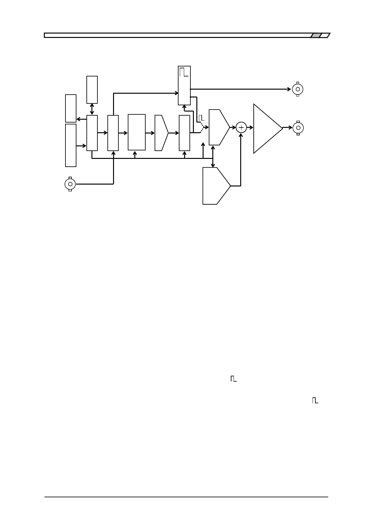
1.4 Operating Principle
DF1906
1.4 Operating Principle
Figure 1-1 Block Diagram
・ CPU performs analog control, such as display panel control, panel key and dial process, USB
remote control process, DDS control, amplitude, and DC offset.
・ DDS (Direct Digital Synthesizer) generates digital data at the set frequency.
・ Waveform Memory converts the digital data from the DDS to standard waveform or arbitrary
waveform data.
The waveform data is set from the CPU. The update rate of waveform data is approx. 6.872 MHz.
・ The waveform data acquired in this way is converted to an analog signal by the D/A converter.
・ LPF (Low Pass Filter) smoothens a staircase waveform output by the D/A converter.
The analog bandwidth (at the -3dB) for arbitrary waveforms and sine wave and ramp wave in the
burst/trigger/gate oscillation mode is approx. 650 kHz.
・ For a square wave at a duty ratio of 50% and at a frequency of 10 kHz or more, a low jitter square
wave is obtained by generating a sine wave by the Waveform Memory-D/A Converter-LPF and
converting it to a square wave by an analog comparator in the generator.
・ For a square wave at a duty ratio of other than 50% or at a frequency of less than 10 kHz, a logic
signal with a duty variable pulse generated by the DDS is converted to a square wave by the
generator. This includes a one-clock (approx. 150 ns) jitter of the DDS.
・ The amplitude is set in the amplitude controller. The DC generator generates a DC offset, which is
added and amplified in the output amplifier to output a signal.
Control
Amplifier
Memory
YNC OUT