3.5. Basic Operations
DF1906
3.5.6 Select Waveform
The DF
1906 allows you to select a total of 8 types of waveforms: sine wave/ramp wave/square
wave/DC, as well as 4 types of arbitrary waveforms (ARB).
When you press waveform selection key [FUNCTION] , move the cursor to the waveform display, and
turn the [MODIFY] dial, the waveform can be selected.
The waveform is displayed in the lower left part of the display for the sine wave/ramp wave/square
wave. Only for a ramp wave with a symmetry of other than 50% or a square wave with a duty ratio of
other than 50%, "Var " is also displayed on the right of the waveform display.
Set Symmetry
"4.1.1 Set Symmetry (Ramp wave)"
Set Duty Ratio
"4.1.2 Set Duty Ratio (Square wave)"
For example, "<ARB1>" to "<ARB4>" are displayed in the lower left part of the display for arbitrary
waveforms 1 to 4.
Write Arbitrary Waveform Data
"5. USB Interface"
When the waveform is set or changed, oscillation stops while it is being set or changed.
3.5.7 Select Oscillation Mode
The DF
1906 allows you to select the three modes: burst/trigger/gate oscillation, in addition to the
continuous oscillation.
When you press oscillation [MODE] key, move the cursor to the oscillation mode display, and turn the
[MODIF Y] dial, the oscillation mode can be selected.
The oscillation mode is displayed as follows.
・ "<CONT>" Continuous oscillation: Outputs the selected waveform continuously.
・ "<BRST>" Burst oscillation: Repeats the mark wave number oscillation and space wave number
stop.
・ "<TRIG>" Trigger oscillation: Performs mark wave number oscillation when a trigger is activated.
・ "<GATE>" Gate oscillation: Performs oscillation while a gate signal is input.
The following can be used for a trigger for trigger oscillation and for a gate signal for gate oscillation.
・[TRIG / CLEAR ] key on the front panel (enabled when the key is pressed)
・ External trigger input connector TRIG IN (the effective polarity can be switched)
・ Command from remote control
"5. USB Interface"
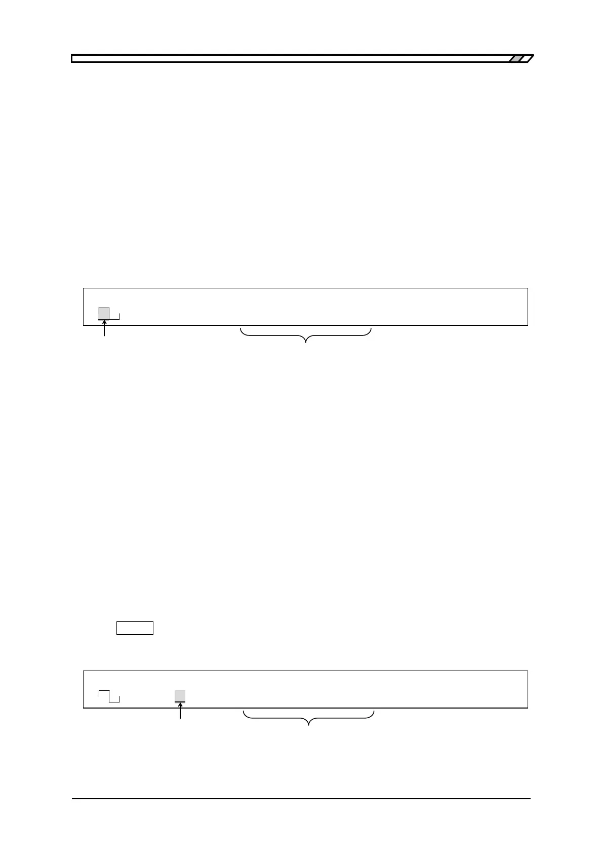
F 500.0000000kHz A 8.000Vp-p O -1.000V
<CONT> Duty 50.0% /OPEN OFF
When cursor is locat ed here,
Symmetry when waveform is ramp wave,
duty ratio when waveform is square wave
F 500.0000000kHz A 8.000Vp-p O -1.000V
<BRST> Mark 50.0 /OPEN OFF
When cursor is locat ed here,
select the oscillation mode
In burst/trigger/Gat e oscillat ion mode,
related items such as phase are displayed/set