3.2 Display at Power On and Initial Settings
DF1906
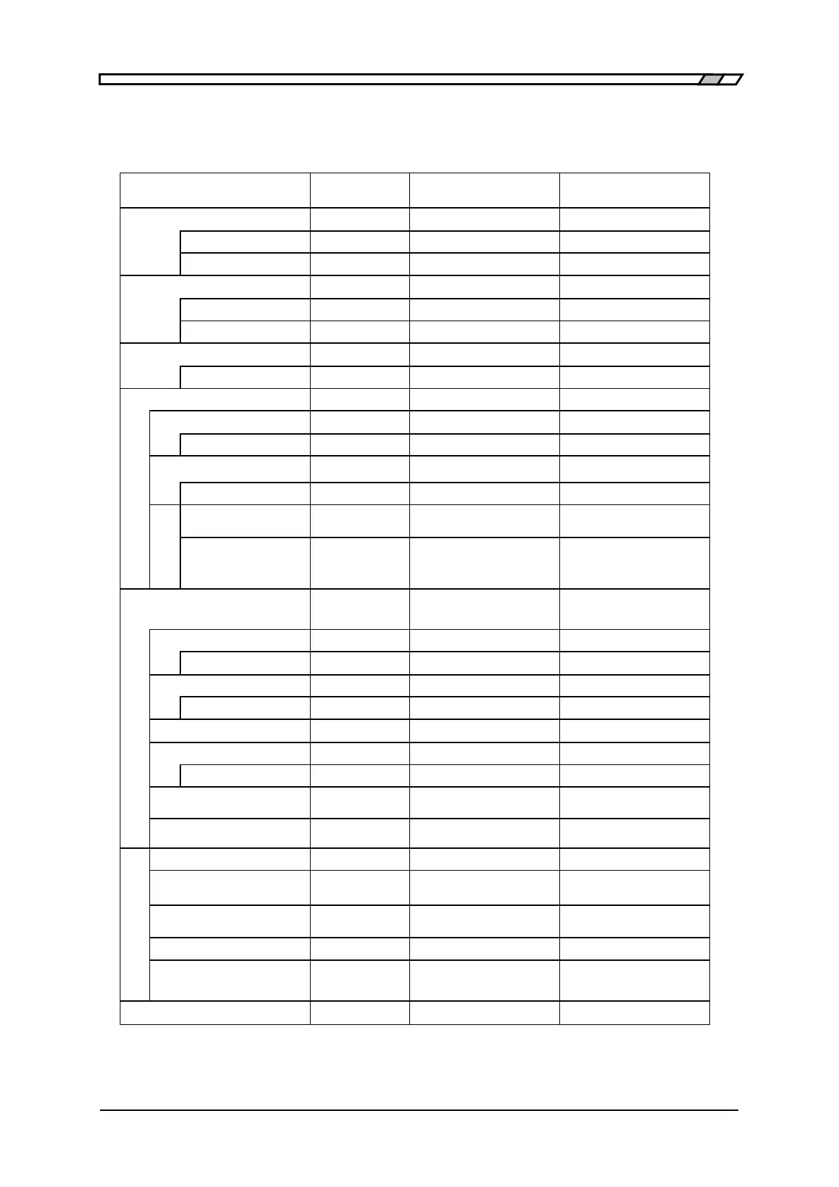
Table 3-1 Initial Settings
The initial setting values are shown in the table below.
Setting item Initial value
Factory default
or data failure
Memory initialized
Cursor Position 0.1V digit ○ ○
Ramp wave symmetry 50% ○ ○
Square wave duty ratio 50% ○ ○
Cursor position 1% digit ○ ○
Select number 1 ○ ○
Arbitrary
waveform data
All 0 ○ —
Oscillation mode
Continuous
○ ○
Cursor position 1 digit ○ ○
SYNC OUT PHASE ○ ○
Phase 0 ゚ ○ ○
゚
TRIG IN Polarity (Trigger)
Fall ○ ○
TRIG IN Polarity (Gate)
Low level ○ ○
Special menu
Memory Contents of
Unselected Memory
○ —
Output when power on PREV ○ ○
High level/
Low level display
OFF ○ ○
○: Initialized -: Not initialized