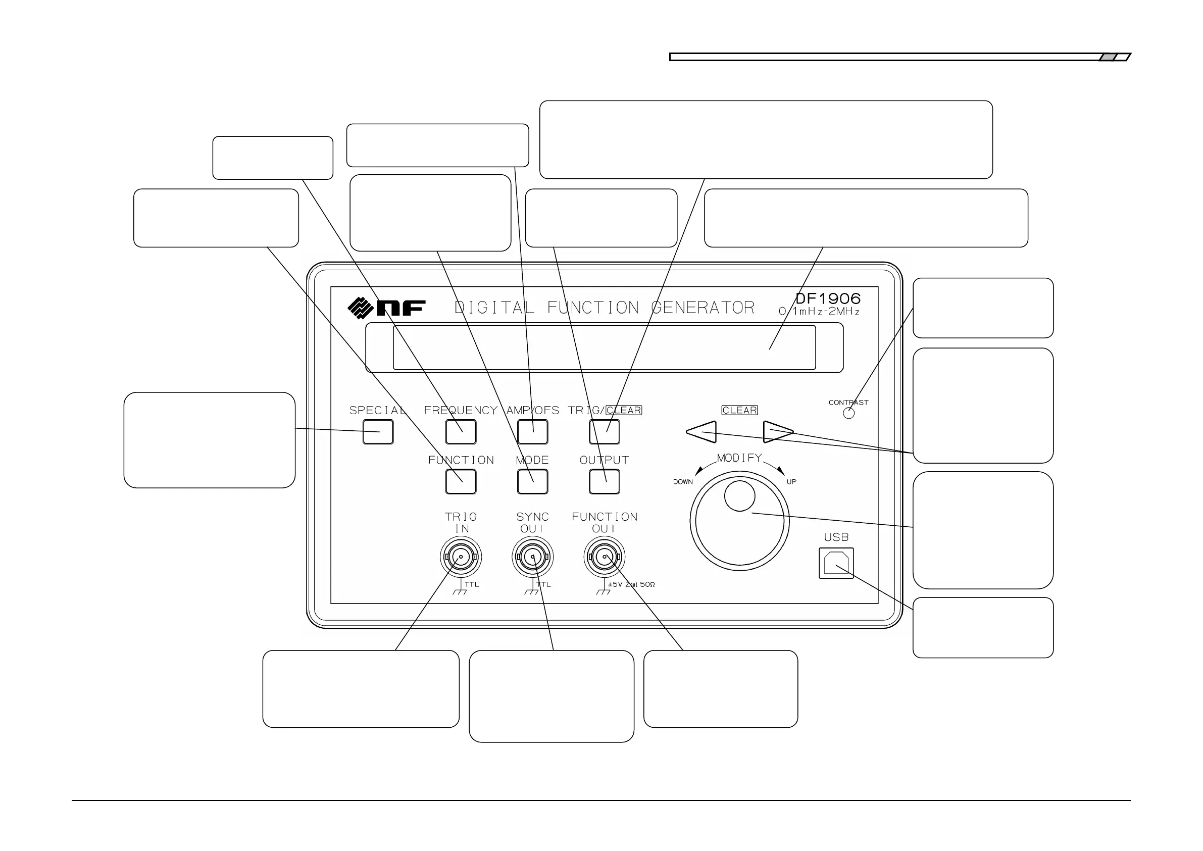
Front Panel
DF1906
Figure 3-1 Front Panel
3.5.4 Set Frequency"
Set the amplitude and DC offset
"3.5.5 Set Amplitude and DC Offset"
3.5.6 Select Waveform"
"4.1 Symmetry and Duty Ratio"
Switch the output between on
and
off
"3.5.8 Select Output On/Off"
r in the trigger/gate oscillation mode "3.5.7 Select Oscillation Mode"
Also used to set the numbers on the left and right of the cursor to zero when setting a numeric value
"3.5.2 Set Numeric Value
"
Also used to clear the setting memory "4.3.1 Setting Memory
"
Select the oscillation mode
3.5.7 Select Oscillation Mode"
4.2 Oscillation Mode-related
Adjust the contrast of the
display panel
Move the cursor left and right
when setting a numeric value
Also used to set the numbers
on the left and right of the
cursor to zero
3.5.2 Set Numeric Value"
frequently changed
parameters; for example, selecting
the setting memory, and displaying
the serial number
Remote control from a PC or
other device via USB
Increase/decrease the number
under the cursor when setting
a numeric value and select a
setting option from the
selection box.
3.5.2 Set Numeric Value"
l to output
3.3.1 Output Connector"
Output a logic signal synchronized
with the waveform or
/trigger/Gate oscillation
3.3 Output Connector"
Provide a trigger signal from an external
source in the trigger/gate
oscillation mode
3.5.7 Select Oscillation Mode"
Display panel for displaying/setting the frequency, amplitude, DC
offset, waveform, oscillation mode, output on/off,
and other parameters "3.5.1 Display"