3.3 I/O Connector
DF1906
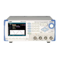
・ Ramp Wave Symmetry Variable
The relationship between FUNCTION OUT signal and SYNC OUT signal when the ramp wave
symmetry is changed is as shown in the figure below. (Upper line: FUNCTION OUT, lower line:
SYNC OUT)
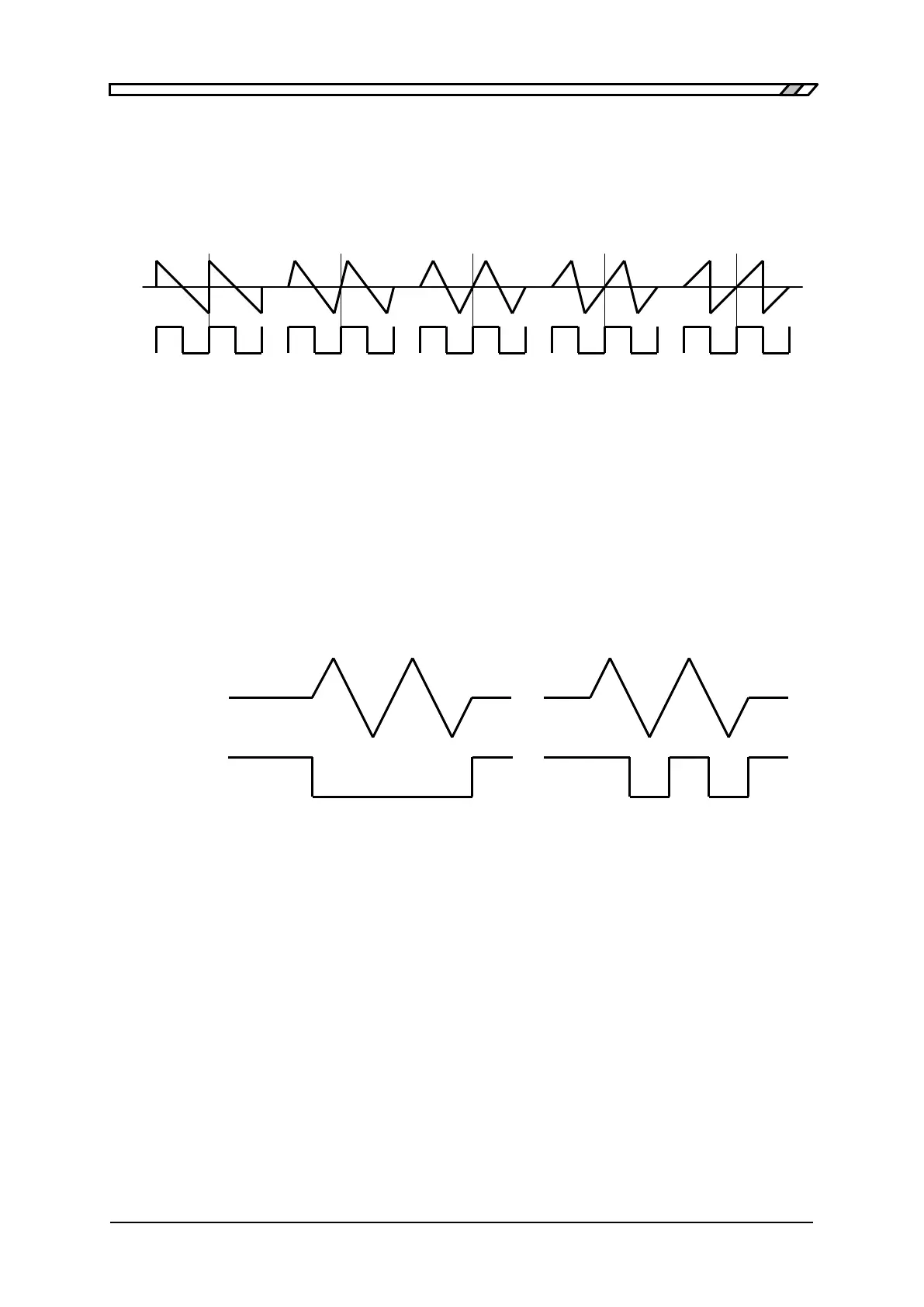
・ At Time of Burst/Trigger/Gate Oscillation
The relationship between FUNCTION OUT s ignal and SYNC OUT s ignal at the time of
burst/trigger/gate oscillation is as shown in the figure below.
(The following figure shows an example of trigger oscillation for the following wave: Phase setting: 0゜,
waveform: Ramp wave with symmetry equal to 50%, and mark wave number: 2.0)
OUT
OUT
When SYNC OUT function is
"STATE"
When SYNC OUT function is
"PHASE"