When dimensioning the collector, consideration must
be given to the geographical location, type of rock and
ground and the degree of coverage provided by the
heat pump.
When installing the collector hose ensure it rises con-
stantly towards the heat pump to avoid air pockets. If
this is not possible, install high points to vent the air.
All brine pipes in heated rooms must be insulated
against condensation. The level vessel (NK) must be
installed as the highest point in the collector system and
on the incoming pipe before the brine pump. Note that
condensation may drip from the level vessel. Position
the vessel so that this does not harm other equipment.
As the temperature of the collector system can fall
below 0 °C it must be protected against freezing down
to -15 °C. One litre of ready mixed brine per meter of
collector hose (applies when using PEM-hose 40 x 2.4
PN 6.3) is used as a guide value when making the vol-
ume calculation.
The level vessel must be marked to show the type of
antifreeze used.
Shut-off valves should be installed as close to the heat
pump as possible. Fit a particle filter to the incoming pipe.
In the case of connection to an open groundwater sys-
tem, an intermediate frost-protected circuit must be
provided, because of the risk of dirt and freezing in the
evaporator. This requires an extra heat exchanger.
Pipe connections 11
FIGHTER 1140
Pipe installation must be carried out in accordance
with current norms and directives. FIGHTER 1140 can
operate up to a return temperature of about 58* °C
and an outgoing temperature from the heat pump of
about 70* °C. The compressor produces up to 65* °C,
the rest is obtained using additional heating.
* Applies to 5 kW 1-phase and 6 - 17 kW 3-phase 3 x 400 V.
The other heat pumps has a max return temperature
of approximately 50 °C and an outgoing max tempera-
ture from the heat pump of approximately 60 °C.
Since FIGHTER 1140 is not fitted with shut-off valves,
these must be fitted outside of the heat pump to facili-
tate servicing.
General
Pipe connections (collector)
The heating medium pump (VBP) runs at the same
time as the brine pump (KBP) with fixed condensing
(docking option 4) in auto mode.
Heating medium pump
NOTE!
The pipe system needs to be flushed
out before the heat pump is connected
so that debris cannot damage
component parts.
Pipe connections for the heat medium side are made
at the top. All required safety devices, shut-off valves
(as close to the heat pump as possible), and particle
filter (supplied) are fitted.
You should fit either an overflow valve or remove
some of the thermostats when connecting to systems
with thermostats on all the radiators (coils).
Pipe connections
(heating medium)
The equipment can be supplemented with a fan coil
unit to make the connection of free cooling possible.To
avoid condensation, all pipes and other cold surfaces
must be isolated with diffusion-proof material.Where
the cooling demand is high, fan convectors with drip
trays and drain connection are needed. The collector
circuit should be fitted with a pressure expansion ves-
sel
. If there is a level vessel, this should be replaced.
Free cooling
Brine in
Brine out
Brine in
Brine out
Fan convectors
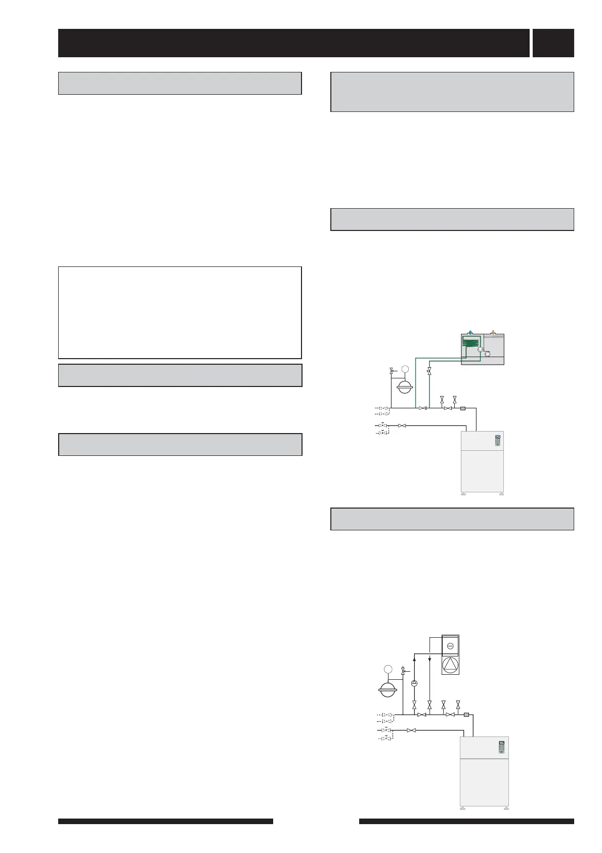
The installation can be supplemented with the exhaust
air module FLM to provide ventilation recovery. To
avoid condensation, all pipes and other cold surfaces
must be isolated with diffusion-proof material. The col-
lector circuit should be fitted with a pressure expan-
sion vessel
. If there is a level vessel, this should be
replaced.
Ventilation recovery
Extract air
Ø 160
Exhaust air
Ø 160