Front panel4
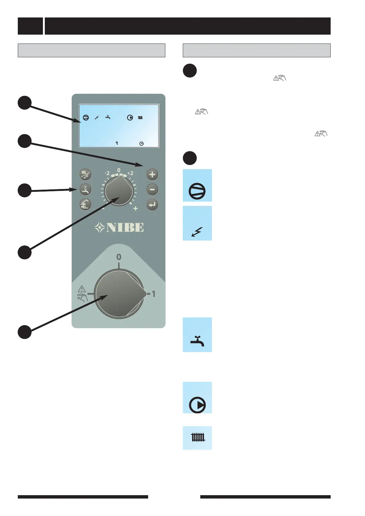
Display
Switch
Left
keypad
Heating
curve offset
Layout
A
B
C
D
Right
keypad
E
Explanation
Switch
with three positions 1 - 0 - :
1 Normal mode. All control functions connect-
ed.
0 The boilers is completely switched off.
Standby Only the circulation pump and pos-
sibly the electrical addition. Not connected
at the factory
The switch must not be turned to “1” or “ ”
before filling the boiler with water.
A
Display First row:
Compressor symbol
Indicates when the compressor is opera-
tional.
Addition symbol
Indicates when the immersion heater is
connected. The line indicates which power
step/steps are currently connected.
I Step 1 is connected.
II Step 2 is connected.
III Step 3 is connected.
I II Steps 1+2 are connected.
II III Steps 2+3 are connected.
I III Steps 1+3 are connected.
I II III Steps 1+2+3 are connected.
B
Hot water symbol.
Tap is shown when the heat pump charges
the hot water.
A is shown when a temperature increase is
in progress.
B is shown when a time based temperature
increase is in progress, for example, peri-
odic.
Circulation pump symbol.
I Shown when the circulation pump is
operational.
II Shown when circulation pump 2 is oper-
ational (the accessory ESV 21 is required).
Heating system symbols
Shown when house heating is in progress.
Second row: Value of the current parameter.
Third row: Description of current display para-
meter. “Hot water temp” is normal-
ly shown.
FIGHTER 1140