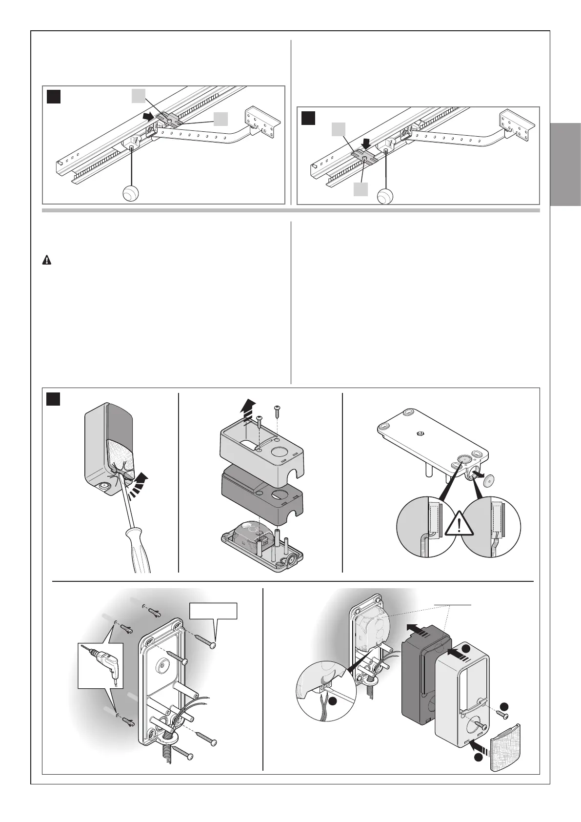
10. Assemblethetwo[P]and[R]stopblocksiftheyarenotas-
sembled.
11. Loosenthescrewsofthetwomechanicalstops,thenmove
thefrontmechanicalstop[P]infrontofthecarriage(g. 22).
Q
P
22
12. Pushthecarriageintheclosingdirectionand,onreachingthe
position,tightenthescrew[Q]fullydown.
13. Manually open the door to the required opening position,
movetherearmechanicalstop[R]nexttothecarriage(g. 23)
andtightenthescrew[Q]fullydown.Important!-Makesurethe
releasecordcanbepulledbelowaheightof1.8m.
Q
R
23
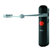
04. - Positionthelowercasinginthepointwherethetubeforthe
passageofthecablesarrivesandmarktheperforationpoints
(Phase 04 - Fig. 23)
-Useapercussiondrilltodrillthewallwitha5mmbit.Insert
the5mmwallplugs(Phase 04 - Fig. 23)
- Passtheelectricalcablesthroughtherelevantholesand
fastenthelowercasingwiththescrews(Phase 04 - Fig. 23)
05.-Connecttheelectricalcabletotheappropriateterminals
bothtotheTXandRXphotocells(Phase 05 - Fig. 23).Carry
outtheelectricalconnectionsaccordingtotherequiredfun-
ctionandgure38.
-Putbackinplace,inthefollowingorder,theinnercasing
followedbytheuppercasingtobefastenedwiththetwo
screwsthen,lastly,insertthecoverandexertslightpressure
to close it (Phase 05 - Fig. 23).
3.2.4 – PHR00 photocells (optional)
Caution:disconnectthepowersupplytothesystembefore
performinganyinstallationoperations.
• position each photocell 40/60 cm above the ground
• position them on the opposite sides of the zone to be
protected • position them as close as possible to the
door (maximum distance = 15 cm) • a tube for passing the
cables must be present in the fastening point • orient the
TX transmitter towards the central zone of the RX receiver
(allowed misalignment: maximum 5°)
01.Removethefrontglass(Phase 01 - Fig. 23)
02.Removetheuppercasingthentheinternalcasingofthepho-
tocell(Phase 02 - Fig. 23)
03.Perforatethelowercasinginthepointwherethecables
shouldpass(Phase 03 - Fig. 23)
23
1
Led SAFE
3
2
4
Ø 3,5 mm
˜
01.
04.
02. 03.
05.
English–11
English