7
GB
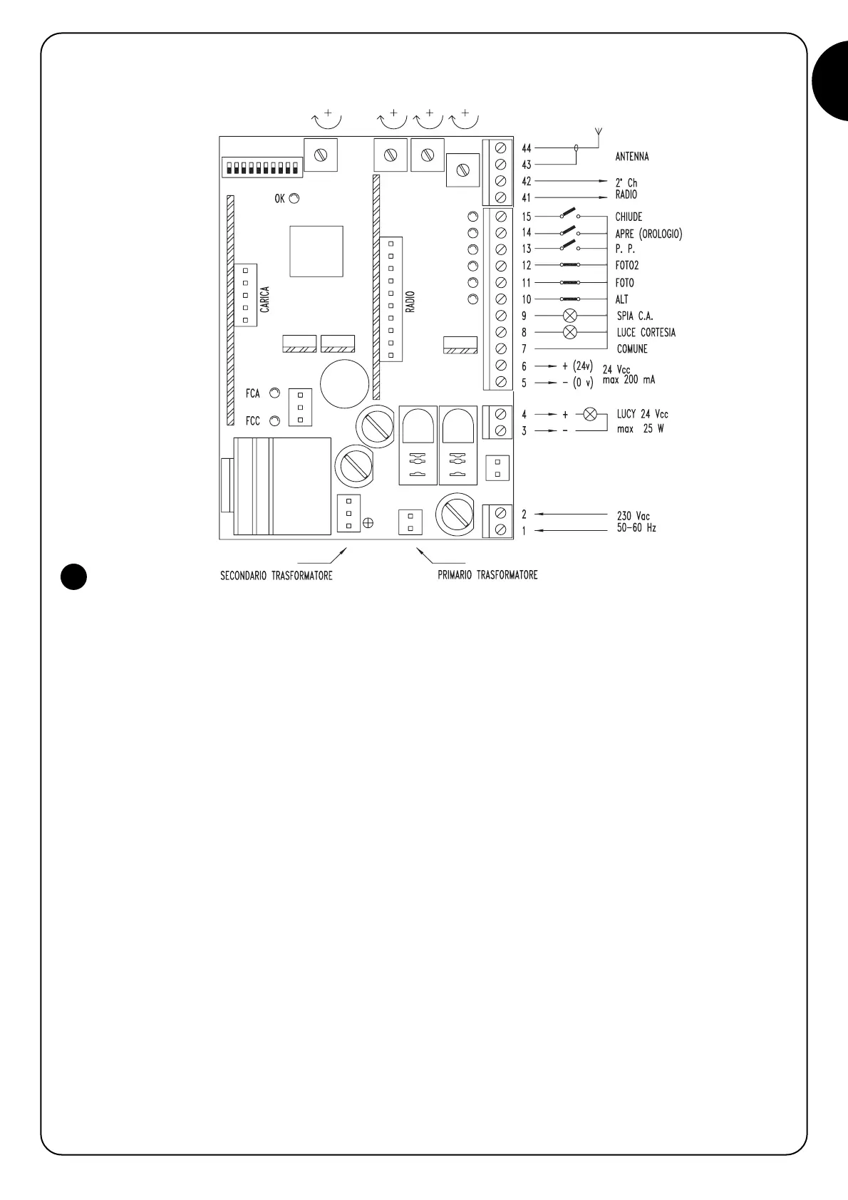
3.3) Description of the connections
Here is a brief description of the possible connections of the unit to the outside:
1-2 : 230 V a.c. = 230 V a.c. 50/60 Hz
3-4 : Flashing light = Output for connection to the 24 V d.c. flashing light, maximum lamp power: 25 W
5-6 : 24 V d.c. = 24 V d.c. output for supplying accessories (Photocell, Radio, etc.) maximum 200 mA
7 : Common = Common for all inputs (terminal 6 can also be used as the Common)
8 : Courtesy Light = 24 V d.c. output for the courtesy light, maximum output power 10 W
9 : C.A. Indicator = Input with STOP function (Emergency, shutdown or extreme safety)
10 : Stop = Input for safety devices (Photocells, pneumatic edges)
11 : Photocell = Input for safety devices with triggering in the opening phase (Photocells, pneumatic edges)
12 : Photocell2 = Input for safety devices with triggering
13 : Step-by-Step = Input for cyclic functioning (OPEN STOP CLOSE STOP)
14 : Open-Timer = Input for opening (which can be timer controlled)
15 : Close = Input for closing
41-42 : 2nd radio channel = Output for the second radio receiver channel if existing
43-44 : Aerail = Input for the radio receiver aerial
The remaining connections are done in the factory but for the sake of completeness here is the list:
TRANS.PRIM. = Primary of the power transformer
TRANS.SECOND. = Secondary of the power transformer
MOTOR = Output for 24 V d.c. motor connection
There are an additional two slots for optional cards:
RADIO = Slot for Nice radio receivers
CHARGE = Slot for battery charge card
3