Serial Hall Call
42-02-7223 C1 5-17
5
iControl DC
Serial Hall Call
Serial I/O allows hall call buttons/indicators to be connected to iControl using a single 2-wire
bus per riser. The serial bus uses a +/- 15-volt square wave, sampled for both amplitude and
duty cycle, for communication between devices. The positive-going signal actually reaches +40-
volts and is regulated to +24-volts to drive hall call lamps or other loads.
A “bus driver” is required for each riser (up to 4 risers) to provide the capacity to carry the load
of multiple, simultaneously lighted lamps. A single controller can have up to four drivers/serial
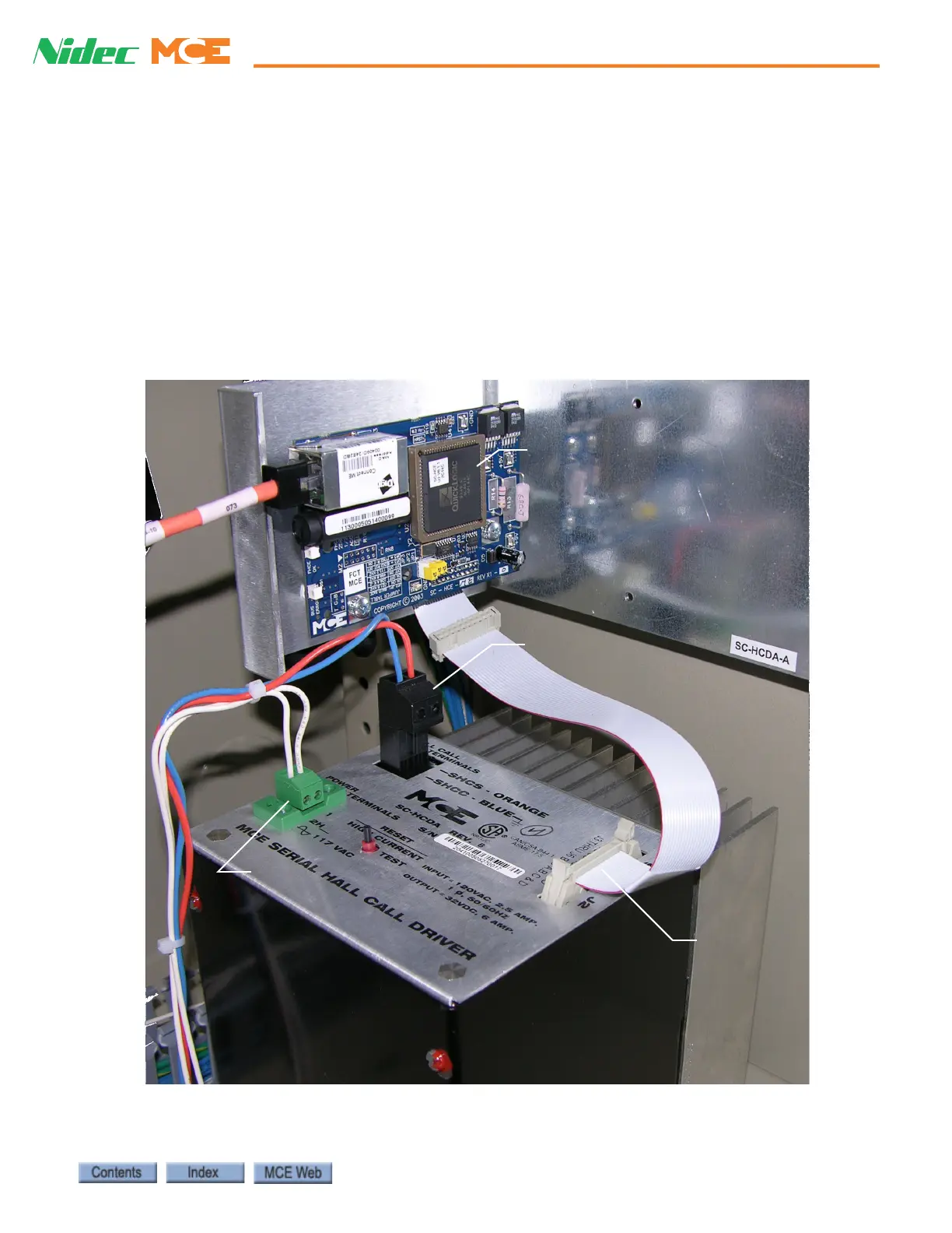
buses with each bus addressing as many as 980 devices. The photograph below shows a serial
hall call bus driver installed in an iCentral Controller cabinet.
Figure 5.5 Serial Hall Call Bus Driver
Serial Bus connection
117 VAC power to driver
Serial output
from driver
Serial to TCP/IP conversion
for connection to System
switch. The board in your
system may be physically
different than this example.

 Loading...