Construction Mode
2-26 Manual # 42-02-7223 C1
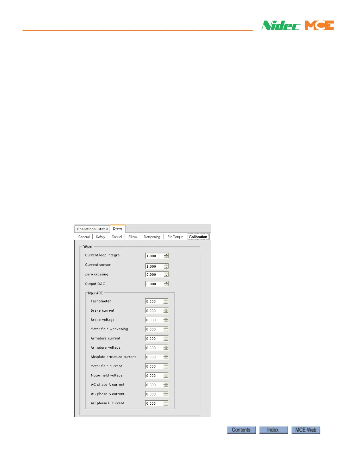
2. Follow the on-screen instructions, “To perform the drive offsets calibration, ...” (cali-
brates Input ADC, Output DAC, Current Sensor, and Current Loop Integral Offset).
3. Once the calibration is Done, the offset values shown on the Setup > Drive tab should
match those shown on the Drive Configuration tab (Configuration > Drive > Calibration
tab).
Manual Drive Setup Procedure (System 12 SCR Drive)
MCE recommends first performing the Automated Drive Setup Procedure previously described
and then verifying the most critical offsets (Output DAC, Current loop integral, Current
sensor and Input ADC - Tachometer) using the manual procedure. However, if the auto-
mated procedure is unsuccessful, the manual procedure must be used. Before adjusting the
drive, verify:
• CONTROLLER STOP switch is in the RUN position
• iBox Safety OK LED is ON
• iBox Door Locked LED is ON
• iBox Fault LED is OFF
• Motor Field has been calibrated (see “Motor Field Calibration (System 12 SCR Drive)”
on page 2-29.)
• iView is connected, write privilege has been obtained (Write Privilege > Acquire
selected and “Yes” softkey on iBox pressed in response).
1. Display the Configuration > Drive > Calibration tab.