Final Adjustment
4-22 Manual # 42-02-7223 C1
Load Weigher Sensor Adjustment
Review the installation and adjustment instructions for the load weigher and verify that all
steps have been completed, including:
• Rope Tension Sensing Load Weigher - perform the procedures described in the EMCO
Load Weigher instruction.
• Crosshead Deflection Load Weigher - perform the procedures described in the “Adjust-
ments” section of the K-Weigh Instruction Manual.
• Isolated Platform Load Weigher - perform the adjustment procedures described in the
MCE Load Weigher instruction.
Next, verify that the iBox is receiving the load weigher signals properly.
1. On Independent service, move the car
to the landing at which the test
weights are stored.
2. On the iView Virtual Oscilloscope
screen, select Load Weigher (Raw) on
Test point 1.
3. With the car empty, verify that the
Test point 1 reading is at least 0.5 but
not greater than 1.5.
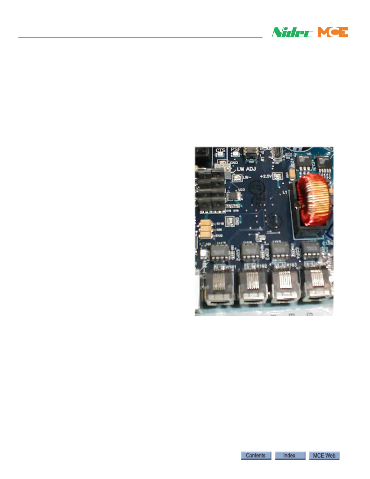
4. Place a full load in the car. Verify that
the Test point 1 value is now between
5.5 and 8.0. If necessary, adjust trim-
pot LW ADJ on the CTP (cartop)
board in the iLink enclosure to achieve
the correct reading.
Pretorque Adjustments - Balanced Mode Method
1. Place a balanced load in the car (the balanced load weight recorded when performing
the Counterweight Balancing procedure). Please refer to “Counterweight Balancing” on
page 3-12.
2. With the car in Test mode (iBox TEST switch ON) move the car to the top floor. All other
inspection modes must be inactive (i.e. cartop, in-car, access, etc.)
3. On the Configuration > Drive > Pretorque tab, enable the Pretorque option and send the
new selection to iControl.
4. On the Virtual Oscilloscope, select Load Weigher Balanced on Test point 1. If necessary,
adjust the windows so that you can see the oscilloscope and the Pretorque parameters at
the same time.

 Loading...