Construction Mode
2-40 Manual # 42-02-7223 C1
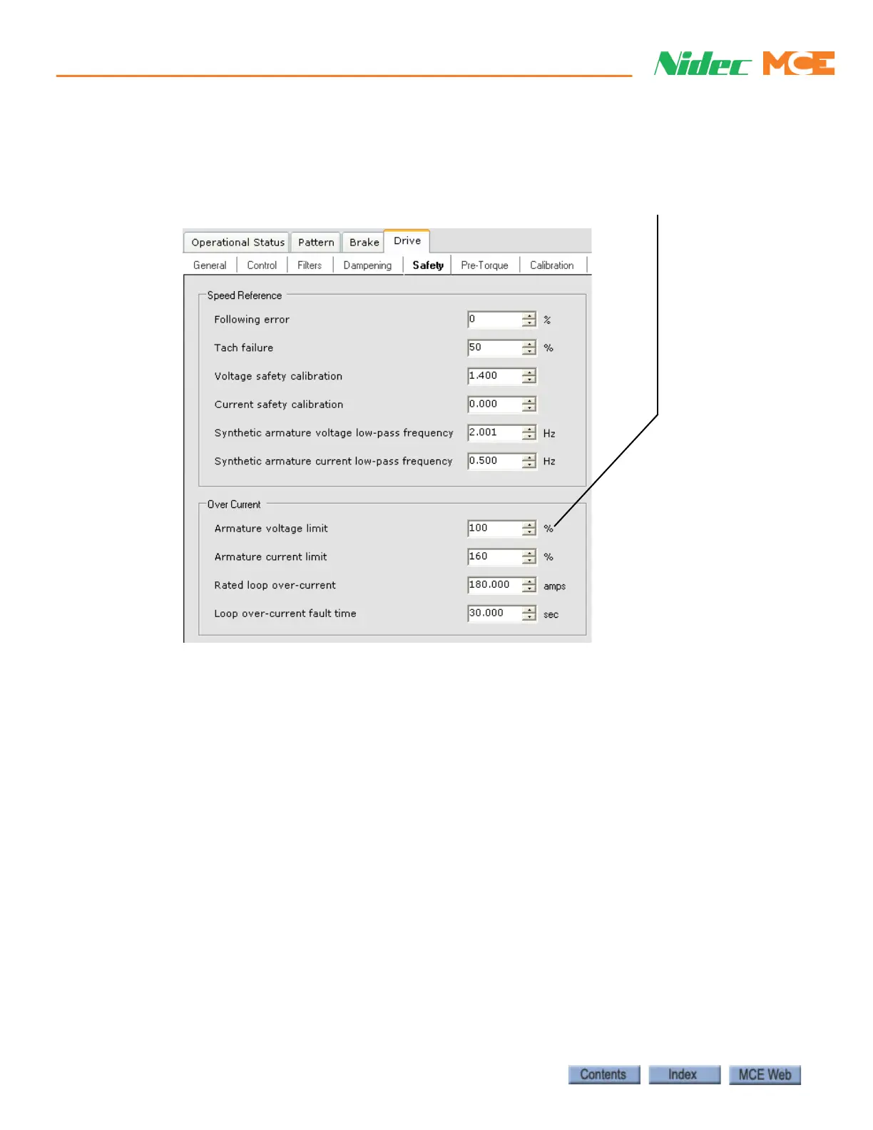
Armature Voltage Limit (System 12 SCR Drive)
• Calculate and set the Armature voltage limit for the job (Configuration > Drive > Safety
tab) using the formula: (Motor Rated Armature Voltage ÷ Displayed Header Voltage) x
100. Set the Armature voltage limit to the calculated value and Send the setting to iCon-
trol. (Example: (350 ÷ 400) x 100 = 87.5, set Armature voltage limit to 87%.)
Armature Current Limit (System 12 SCR Drive)
1. Verify that the Armature current limit setting is near the default setting of 160%.
2. Run the car and observe the System 12 drive Current Limit LED. If the LED lights,
increase Armature current limit in 5% increments until the LED stays off when the car
is run. (Remember you must Send changes to iControl before they take effect.) You
should not have to go above about 180% if the car is counter-balanced correctly.