Construction Mode
2-44 Manual # 42-02-7223 C1
Tach Error Tripping Threshold Adjustment
1. On the iView Virtual Oscilloscope, set Test point 1 to Speed Feedback and Test point 2 to
Tach Error Upper Limit.
2. On Inspection, run the car several times between floors in both directions. Monitor the
traces and verify that the Speed Feedback and Tach Error Upper Limit traces track but
remain comfortably separated.
3. Set Test point 2 to Tach Error Lower Limit.
4. On Inspection, run the car several times between floors in both directions. Monitor the
traces and verify that the Speed Feedback and Tach Error Lower Limit traces track but
remain comfortably separated.
5. Estimate the smallest percentage of Following error that would allow the Feedback and
Limit traces to remain separated.
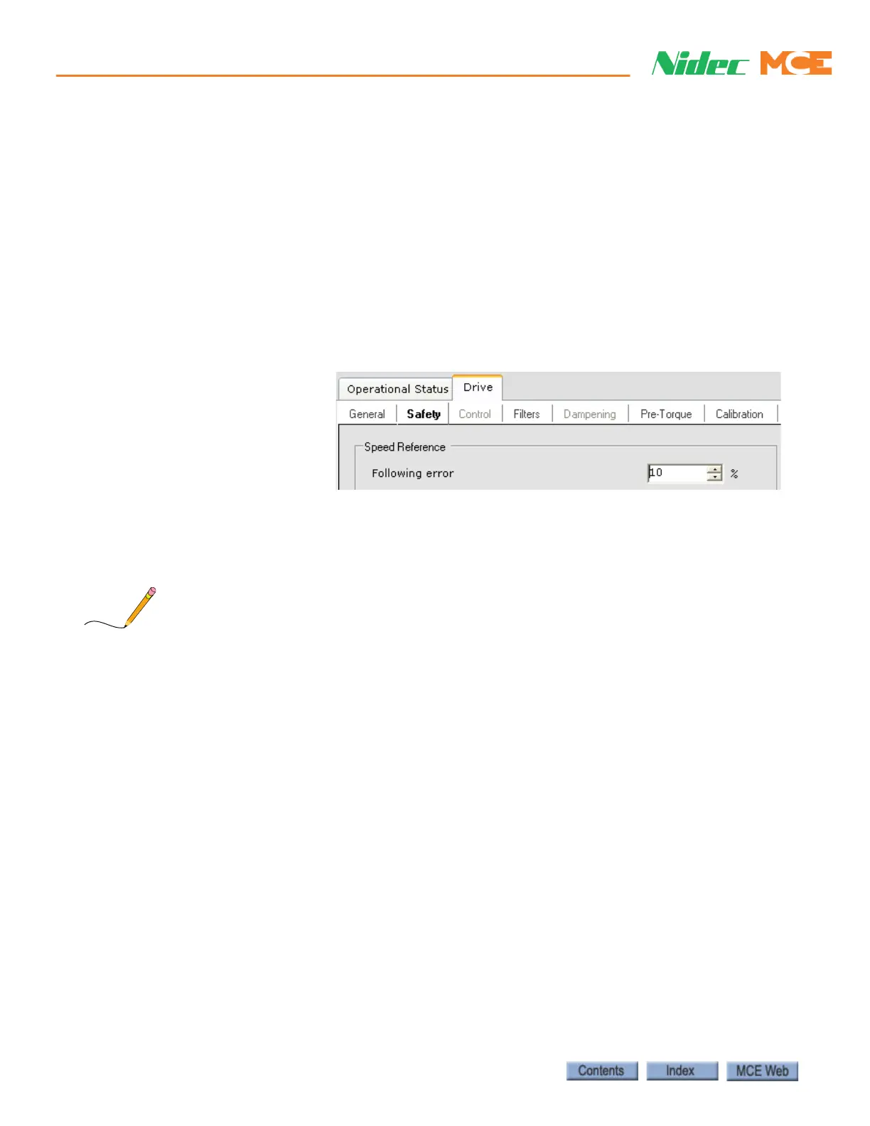
6. Increase the calcu-
lated value by 1/2
and set Following
error to this value.
For example, if the
calculated percent-
age is 6%, add that to
1/2 of 6 (3) and set
Following error to 9%. Remember to send the change to iControl.
7. Repeat steps 1 through 4, verifying that Feedback and Limit traces remain separated. If
they do not, recalculate and reset Following error.
A Following error setting of 10% is fairly typical. Keep in mind that the Following error margin
is a percentage of commanded speed. On a 500fpm job a 10% Following error allows a 50fpm
deviation from contract speed before a fault is generated.