Serial Hall Call
42-02-7223 C1 5-19
5
iControl DC
Hall Call Installation
Installing a serial hall call system includes:
• Pulling the serial bus wiring
• Setting the node board addresses
• Installing the hall call enclosures (refer to the job prints)
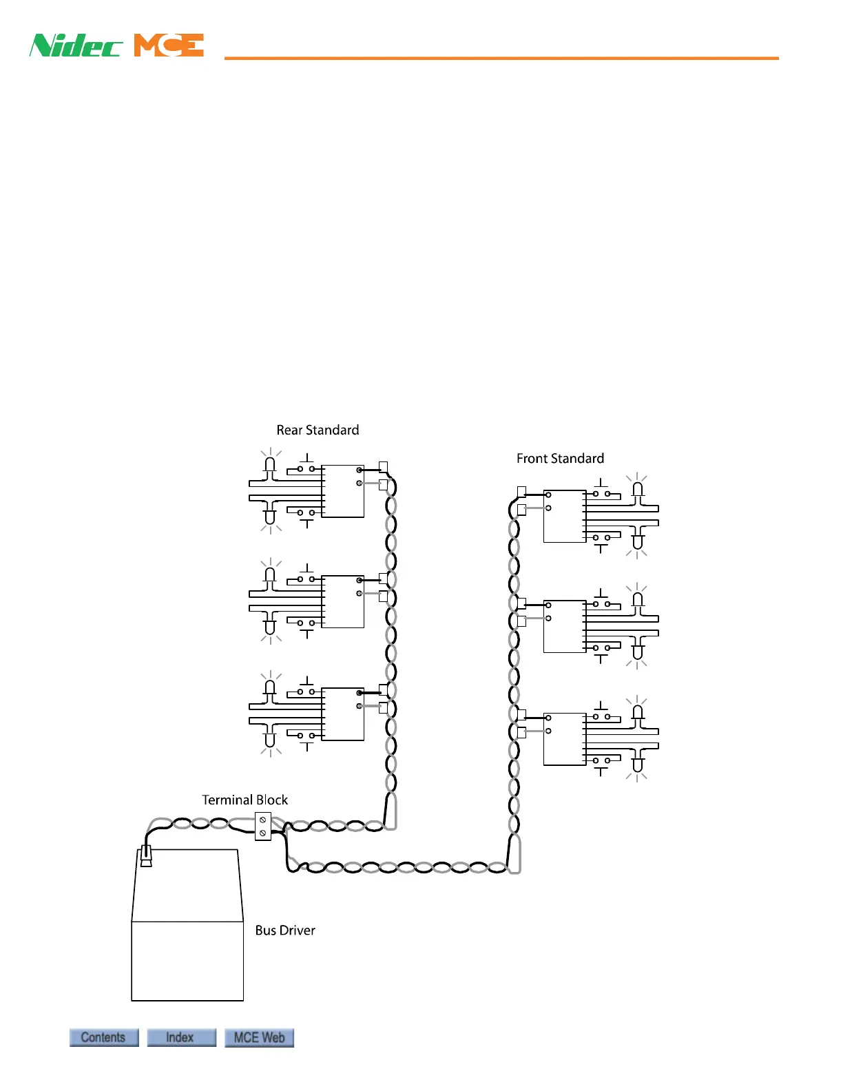
Pulling Serial Bus Wiring
The serial bus is the physical, twisted pair of 14 AWG or 16AWG wires along which all the hall
calls are connected. Install the serial bus wiring in accordance with applicable codes. The best
practice is to initiate each separate vertical bus wire run from the controller location. If neces-
sary, multiple serial bus runs can be “paralleled” at a driver to make them a single serial bus.
Refer to the drawing “Serial Hall Call Suggested Wiring Methods” in the job prints for specific
instructions for each job. The illustration below shows a single serial bus connected to serve two
vertical runs of hall call boxes.
Figure 5.8 Single Bus, Two Vertical Runs of Hall Call Boxes

 Loading...