Installing the Load Weigher
42-02-7223 C1 3-5
3
iControl DC
Installing the Load Weigher
Install and adjust the provided load weigher as directed in the instructions accompanying the
load weigher. Information regarding load weigher selection and threshold settings is provided
in Section 4. Please refer to “Load Weigher Adjustment for Dispatching ” on page 4-38.
Installing Brake Monitoring
Brake monitoring via an independent contact is required by code only for disc brakes. A spare
iBox input (SP2D), or a programmable input (Brake Switch) on an ICE-MIAC board, may be
used for the brake contact. The brake monitoring contact may be provided as part of the brake
assembly. If not, a micro-switch (rated for at least 1/4 Amp, 125VDC) must be provided by the
installer and mounted such that when the brake picks, the switch activates (see note below).
Refer to job prints for electrical connection information.
The brake monitoring contact provides a path between the iBox 110VDC (#3) bus and the SP2D
or Brake Switch input. If the brake fails to pick (or drop) at the proper time, this signal will
cause the controller to generate a Brake Pick Fault (See “Brake Pick Fault, BRAKE PICK
FAULT” on page 6 - 18.) or Brake Drop Fault (See “Brake Drop Fault, BRAKE DROP FAULT”
on page 6 - 17.). The fault message is shown on the iBox LCD display, on the iView Operational
Status tab and in the iView Event Log.
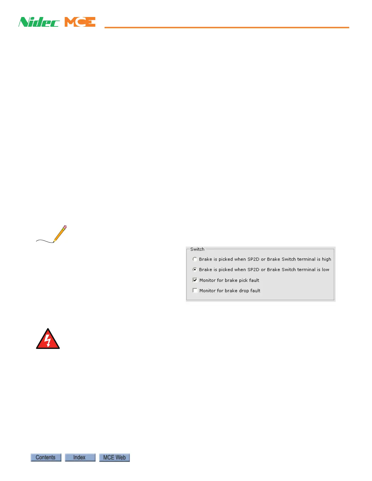
On the iView > Controller > Configuration
> Brake > Control tab, switch parameters
are provided to specify the polarity of the
SP2D/Brake Switch input (active high or
low). In addition, parameters direct the
system to monitor for a brake pick and/or
brake drop fault. If neither pick or drop
monitoring are checked, the controller will
ignore the SP2D/Brake Switch input.
When installing the switch, take all necessary precautions not to interfere with normal brake design
or operation.

 Loading...