Inspection Mode
3-2 Manual # 42-02-7223 C1
Landing System
Please see the instruction shipped with the landing system equipment. See the job prints for
wiring instructions. Depending on job requirements, one of the following landing systems will
be used:
• iLand: Wheel encoder system. Instruction 42-IS-0173.
• LS-EDGE: Steel tape encoder system. Instruction 42-IS-0214.
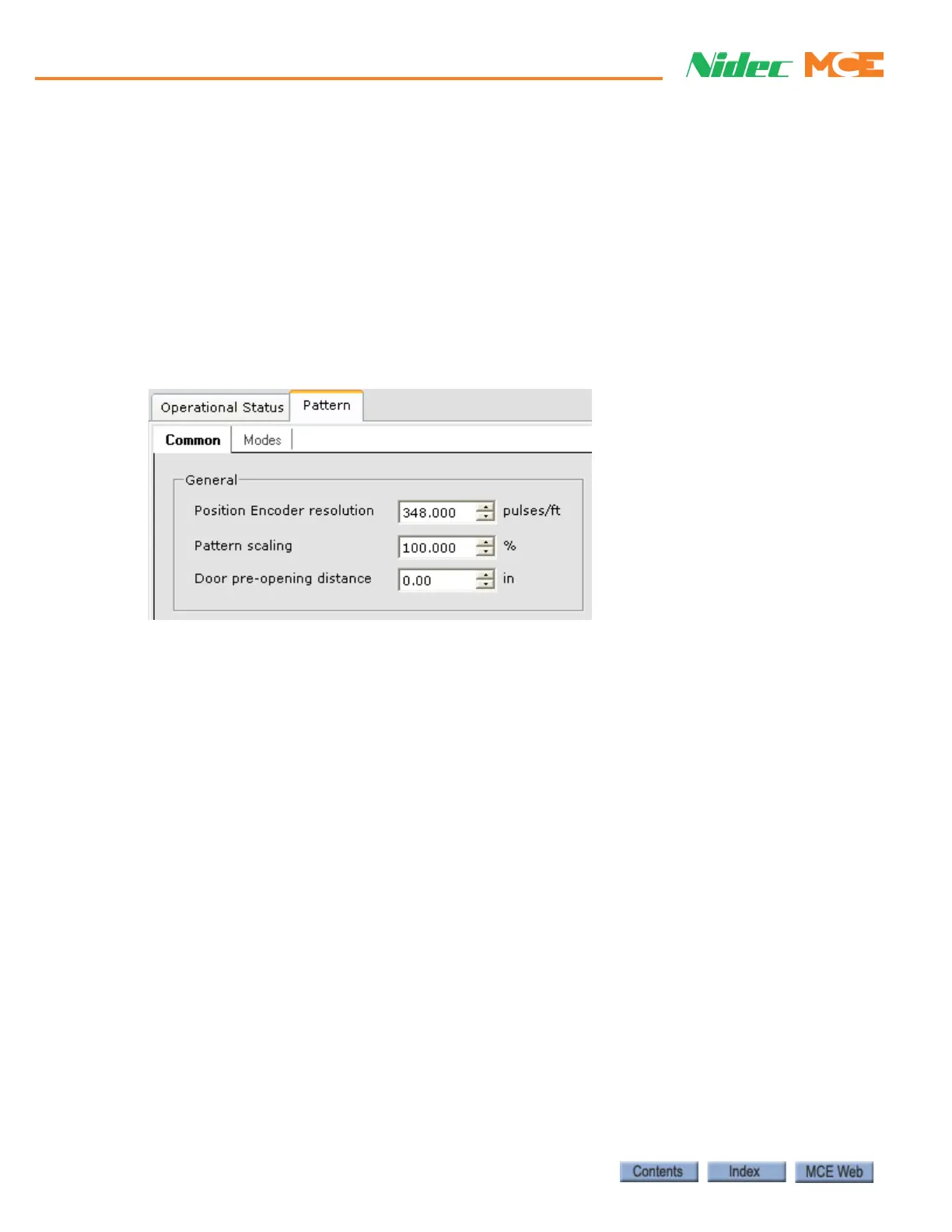
Setting the Position Encoder Resolution parameter
For the iLand Compact landing system, the Position Encoder resolution parameter must be set
to 348 pulses per foot (iView Controller > View > Configuration > Pattern > Common tab).
Calibrating the Floor Offsets
See “Calibrating the floor offsets” in Section 4. If this is a new installation, wait until the car has
been fully adjusted so that it stops consistently and accurately at the floors.
Installing iLink
iLink is the cartop interconnect box used with iControl systems. The illustration below shows a
view of iLink circuitry with the cover removed. Make connections to the interconnect box as
shown in your job prints.

 Loading...