DC Hoist Motor, Brake, and Encoder/Tachometer
42-02-7223 C1 2-13
2
iControl DC
Velocity Encoder Installation and Wiring
(If you are using a tachometer, please see the preceding topic.) The encoder must be mounted
and wired according to the drawings. When installed, the encoder must be electrically isolated
from the motor or any other ground. (Resistance between the encoder casing and the motor or
other ground should be “infinite.”)
Do not mount the encoder or its wiring close to a magnetic field (the motor or brake coils). Mag-
netic fields can induce AC into the encoder signal, producing erratic control at lower speeds.
Encoder wiring must use a separate, grounded conduit. Inside the controller cabinet, if control
wires must cross power wires, they must cross at right angles to reduce the possibility of inter-
ference.
Encoder Isolation The encoder housing must be electrically isolated from the machine
(ground). To check this:
1. Measure the resistance between the encoder case and the frame of the motor. The mea-
sured value must be “infinite” for complete isolation.
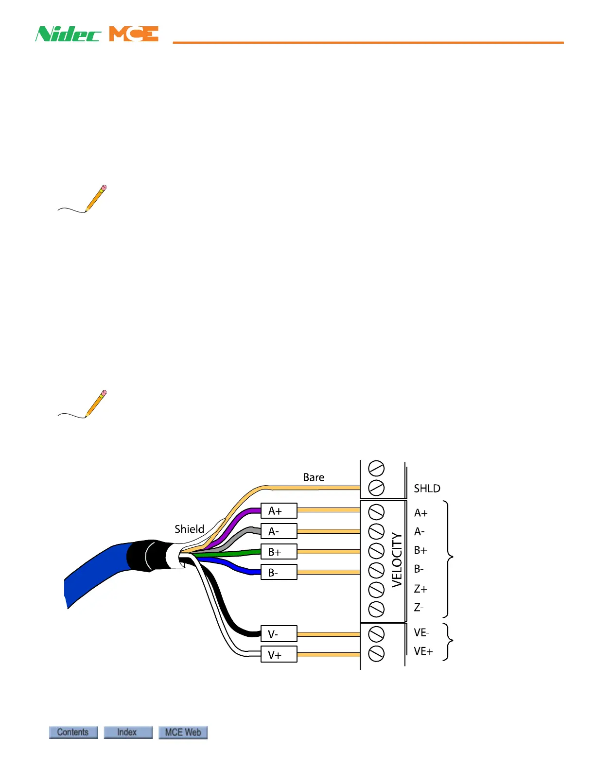
Encoder Wiring A shielded cable with an appropriate connector at the encoder end is
provided. The controller end of the cable exposes trimmed and tinned individual conductors.
The encoder cable must be routed into the controller cabinet in a separate conduit. The follow-
ing illustration shows the encoder wiring at the controller end of the cable.
These connections are shown for illustration purposes only. Follow the job print instructions
for your specific encoder connections — they may be different than those shown here. Z+ and Z-
connections are rarely used at the controller-end.
Quadrature
data from
encoder
Drain/Shield
Power to
encoder
iBox
Purple
Gray
Green
Blue
Black
White