Chapter 1 System Configurations and Part Names
1.4 Name of Each Part
2-20
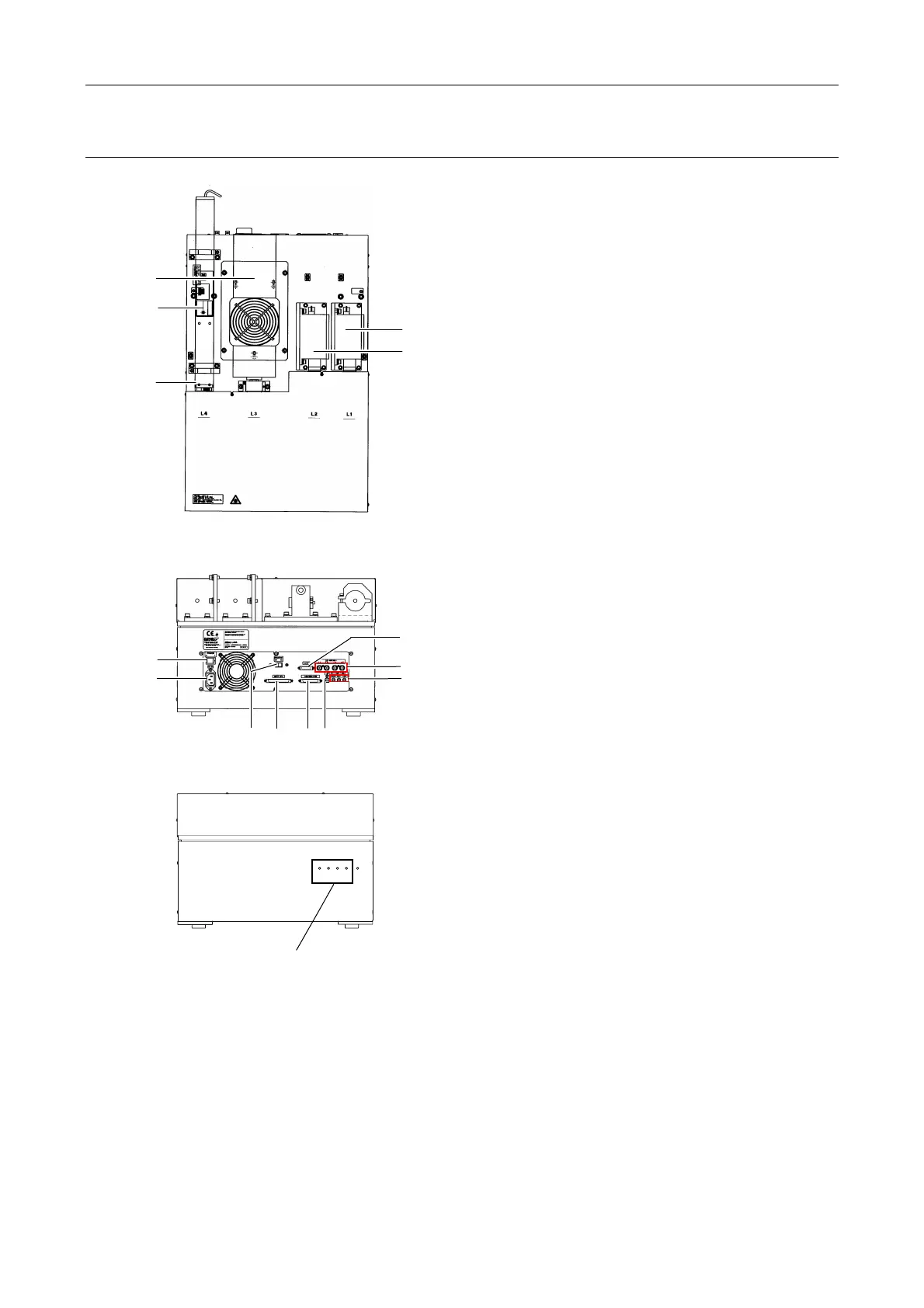
Four-laser module A (LU4A)
Figure 1.4-13
Figure 1.4-14
L4
L3
L2
L1
POWER
Figure 1.4-15
(1) Laser mounting position L1
(2) Laser mounting position L2
(3) Laser mounting position L3
(4) Laser mounting position L4
(5) Single-mode fiber
(6) Power switch
(7) AC inlet
(8) Remote switch
(9) CONTROLLER connector
(Do not use in this system.)
(10) AOTF/PC connector
(Do not use in this system.)
(11) Interlock cable connectors
(12) LUSU connector
(13) USB connector
(14) LD connector
(Do not use in this system.)
* For details of available lasers for each position of laser units, see Table 8.1-2, “Mountable lasers,” in
Section 8.1, “Overall Configuration” in Chapter 8, “Specifications and Performance.”
(3)
(5)
(1)
(4)
(2)
(6)
(12)
(8) (13)
(14)
(7)
(11)
(9)
(10)
Indicating shutter conditions