Chapter 4 Setting Up the Microscope
4.2 Setup Procedure
2-33
5
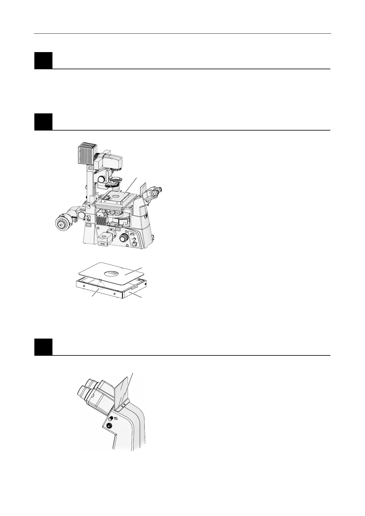
Assemble the remaining microscope parts.
Refer to the instruction manual included with the microscope main body before assembling the
remaining microscope parts.
6
Attach the laser safety cover (TIRF illuminator unit only).
L
A
S
E
R
R
A
D
IA
T
IO
N
A
V
O
ID
E
X
P
O
S
U
R
E
T
O
B
E
A
M
C
L
A
S
S
3
B
L
A
S
E
R
P
R
O
D
U
C
T
A
V
O
I
D
E
X
P
O
S
U
R
E
LA
SER
L
IGH
T
IS
EMIT
TED
FR
OM
O
BJ
EC
TIV
E
A
PERTURE
C
A
U
T
IO
N
–
C
L
A
S
S
3
B
L
A
SE
R
R
A
D
IA
T
IO
N
W
HE
N
O
P
E
N
A
V
O
I
D
E
X
P
O
S
U
R
E
T
O
T
H
E
B
E
AM
V
O
R
S
IC
H
T
–
LA
S
ER
S
TR
A
H
L
U
N
G
K
LA
S
SE
3B
,
W
E
N
N
A
B
DE
C
K
U
N
G
G
E
Ö
F
F
N
E
T
N
IC
H
T
D
EM
S
T
R
A
H
L
A
U
S
S
E
T
ZE
N
A
V
O
ID
E
X
P
O
S
U
R
E
L
A
S
E
R
L
IG
H
T
I
S
E
M
IT
T
E
D
F
R
O
M
T
H
I
S
A
P
E
R
T
U
R
E
C
A
U
T
I
O
N
–
C
L
A
S
S
3
B
L
A
S
E
R
R
A
D
IA
T
IO
N
W
H
E
N
O
P
E
N
A
V
O
I
D
E
X
P
O
S
U
R
E
T
O
T
H
E
B
E
A
M
V
O
R
SI
C
H
T
–
L
A
S
E
R
S
T
R
A
H
L
U
N
G
K
L
A
S
S
E
3
B
,
W
E
N
N
A
B
D
E
C
K
U
N
G
G
E
Ö
F
F
NE
T
N
IC
H
T
D
E
M
S
T
R
A
H
L
A
U
S
S
E
T
Z
E
N
C
A
U
T
I
O
N
–
C
L
A
S
S
3
B
L
A
S
E
R
R
A
D
IA
T
IO
N
W
H
E
N
O
P
E
N
A
V
O
I
D
E
X
P
O
S
U
R
E
T
O
T
H
E
B
E
A
M
V
O
R
S
I
C
H
T
–
L
A
S
E
R
S
T
R
A
H
L
U
N
G
K
L
A
S
S
E
3
B
,
W
E
N
N
A
B
D
E
C
K
U
N
G
G
E
Ö
F
F
N
E
T
N
I
C
H
T
D
E
M
S
T
R
A
H
L
A
U
S
S
E
T
Z
E
N
ON
OFF
6V30W
MAX.
12V100W
Figure 4.2-6
If you are using the TIRF illuminator unit, the motorized
shutter will not open unless the laser safety cover is
attached on the stage. Make sure it is attached in the
prescribed position.
1. Place the laser safety cover body on the stage,
and secure it by tightening the 4 screws with the
Allen wrench.
2. Connect the laser safety cover’s cable to the
safety-cover connector of the TI-LUSU shutter
unit.
3. Attach the cover on top of the body.
The interlock will close the motorized shutter of
the laser unit if the cover is removed during use.
* In the case of the photo activation illuminator unit,
you must attach a specimen cover on the stage
when using episcopic illumination or laser light.
* Touching the interlocking part or getting it wet could
cause it to malfunction.
7
Attach the light shielding plate.
B
Figure 4.2-7
Using an Allen wrench, screw the light shielding plate
onto the eyepiece tube.
Laser safety cover
Upper cover
Body
Safety interlock (both sides)
Light shielding plate