Do you have a question about the Nivus OCM PRO CF and is the answer not in the manual?
Specifies the qualifications and training needed for installation, commissioning, and maintenance personnel.
Defines persons familiar with installation, mounting, start-up, and operation, possessing relevant qualifications.
Lists extra instruction manuals or technical descriptions required for system operation.
Explains the meaning of general warning symbols and signal words used in the manual.
Details essential precautions for safe operation, including germ contamination and power disconnection.
States the manufacturer's right to change document contents and disclaims responsibility for consequences.
Outlines user obligations regarding safety directives, operating permits, and local regulations.
Describes the nameplate information and its importance for queries and orders.
Emphasizes using certified parts and warns against using non-original replacements.
Provides an overview of different OCM Pro CF transmitter versions based on type key.
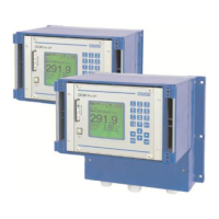
Presents a general overview of the OCM Pro CF, including enclosure types and components.
Specifies the device's intended purpose, lifetime, and application in flow measurement.
Instructions for checking delivery completeness and reporting transit damage.
Lists standard components included in the OCM Pro CF measurement system delivery.
Specifies storage conditions, including temperature, humidity, and protection requirements.
Provides guidance on protecting the measurement system during transportation.
Details the procedure and conditions for returning units to the manufacturer.
Describes the OCM Pro CF as a stationary system for flow measurement and data storage.
Explains the water-ultrasonic level measurement method using transit time.
Details level measurement using a piezoresistive pressure sensor based on water column pressure.
Describes using an external 4-20 mA signal for level input, referencing i-Series sensors.
Explains the ultrasonic burst method for flow velocity detection using piezo crystals.
Describes using radar waves reflected from the water surface for velocity measurement.
General guidelines for proper installation, avoiding specific environmental conditions.
Details on how to securely fasten the wall mount enclosure using screws and dowels.
Provides the physical dimensions of the wall mount enclosure for installation planning.
Covers electrical installation requirements, safety precautions, and wiring standards.
Explains the different transmitter versions and their terminal clamp markings.
Illustrates how to connect flow velocity or water-ultrasonic combi sensors to the transmitter.
Recommends overvoltage protection devices for power supply and mA-outputs for effective protection.
Describes how to connect the panel mount enclosure, including fastening.
Details the process of fastening the panel mount enclosure after cutting the panel.
Provides the physical dimensions of the panel mount enclosure for installation planning.
Shows how to connect sensors to the panel mount enclosure's reverse side.
Illustrates overvoltage protection for power supply and analog inputs/outputs in panel mount enclosures.
Explains how to power the unit using AC or DC supply and the function of slide switches.
Describes the conditions and features required for using the transmitter to control flow rate.
Notes that control technology knowledge is required for controller setup and highlights M4 type features.
Refers to installation instructions for correlation and Doppler sensors for construction details.
Provides a wiring diagram for the regulator mode, showing connections for control and feedback.
Explains the control algorithm, emphasizing the use of all digital inputs for slide valve control.
Details communication options for remote access and data transmission.
Explains communication capabilities, especially remote access via the Internet.
Provides notes to the user, emphasizing manual reading, wiring, and contact information.
Describes the 18-button keypad and its key assignments for data input.
Details the OCM Pro CF's graphic display, resolution, and the meaning of display elements.
Explains menu navigation using control keys and the functions of specific keys.
Explains the process of parameter setting, PIN code usage, and saving/rejecting modifications.
Describes the standard operation mode and its submenus for viewing data and status.
Displays measurement place name, time, flow rate, level, and average velocity.
Indicates velocity distribution in a vertical path and explains interpretation of the profile.
Allows viewing flow totals for the past 7 days and modifying the totalisation interval.
Monitors unit function interruptions, ordering errors by date/time, and allows deletion.
Records average cycle values for level, velocity, and height over past days.
Allows modification of basic screen settings, units, language, and display contrast/brightness.
Enables selection of units for flow, velocity, level, and total values.
Allows selection between metric, English, and American unit systems.
Lists available languages for communication and message indication on the display.
Adjusts display settings like contrast and brightness using arrow keys.
Includes an internal clock for functions; settings can be modified via 'Date' and 'Time' menus.
Allows resetting the totalizer, typically used when replacing a transmitter.
The most extensive menu for OCM Pro CF settings, covering essential parameters.
Defines the measurement place, including name, geometry subdivision, and channel shape.
Allows defining a name for the measurement place, similar to mobile phone text entry.
Enables parameter setting for large special profiles with convex tops into zones.
Allows selection and setting of standard channel profiles like pipe, egg, or rectangle.
Enables input of respective channel dimensions based on the chosen profile.
Considers sludge level as a non-moving sub-area subtracted from the total hydraulic area.
Suppresses lowest movements or apparent volumes, setting values below Qmin to zero.
Defines parameters for level measurement, depending on the selected sensor type.
Describes level measurement using an active air-ultrasonic sensor from top down.
Explains level measurement using water-ultrasound from bottom up with combi sensors.
Covers level measurement using external 2-wire Ex probes like pressure or echo sounder types.
For permanently filled pipes; constant filling level entered for flow calculation.
Level measured using combi sensors with integrated pressure cells from bottom up.
Level measured using external 2-wire sources like NivuMaster or HydroBar probes.
Combines sensor types 1 and 5 for ranges from 0 cm to flood level.
Combines sensor types 3 or 6 with type 5, replacing air-US with a 2-wire probe.
Combines sensor types 2 and 5 for levels from 0.5 cm to flood.
Combines sensor types 1 and 2 for levels from 0 cm up to approx. 80% filling.
Combines sensor types 2 and 6 or 3 for applications similar to water-US + air-US.
Combines options 1, 2, and 5 for high accuracy from 0 cm to overflow.
Combines options 2, 3 or 6 with 5, using 2-wire probe for low levels.
Required parameter for sensors not installed directly on channel bottom.
Covers settings related to flow velocity measurement, including sensor type and position.
Allows changing the sensor type for v-Sensor mode, selecting based on construction.
Allows modification of flow velocity sensor installation height (h) and related parameters.
Configures analog inputs, including channel number, name, function, range, and units.
Selects which analog input (1-4) to configure from the available parameters.
Allows assigning a name to the analog input, saved only on the memory medium.
Assigns functions like archive, set point, or regulator mode to the analog input.
Defines analog input span and weighting via a breakpoint table for signal conversion.
Adds a fixed positive or negative offset to the analog value based on the chosen unit.
Enables setting and assigning digital input signals for regulator operation.
Selects which analog input (1-4) to set, corresponding to the digital input number.
Assigns a name to the digital input, useful for saving on a memory card.
Assigns regulator functions like control close, open, torque, or lock v-measurement.
Toggles between inverse and non-inverse input logic for monitoring end switch connections.
Defines functions and measurement spans for each analog output.
Selects which analog output (1-4) to set based on available parameters.
Assigns a name to the analog output, saved for memory card use.
Assigns functions like flow rate, level, velocity, or temperature output to analog outputs.
Allows toggling between measurement ranges of 0-20 mA or 4-20 mA.
Defines the span of the enabled analog output, allowing negative values.
Defines the analog output condition during errors like cable break or CPU failure.
Defines functions and parameters for individual relay outputs.
Selects which relay (1-5) to configure using the following parameters.
Name is not required here as it's used for internal unit functions only.
Assigns functions like flow rate, level, velocity output, or error messages to relays.
Selects between normally open and normally closed relay logic.
Indicates the menu only if 'Limit contact' function is chosen.
Indicates the menu only if 'Impulses' function is chosen.
Adjusts transmitter for waste water applications, enabling slide valve monitoring.
Enables control unit functions like slide valve monitoring and quick close control.
Allows choosing between internal and external set points for the controller.
Defines the internal set point value in the indicated unit.
Configures external set point parameters like measurement range and linearisation.
Adds a fixed positive or negative offset to the external set point.
Monitors external setpoint for cable breaks and switches to internal setpoint if detected.
Allows modification of logic functions for output relays (relay 4 and 5).
Defines logic function of relay 4 (normally closed or normally open).
Defines logic function of relay 5 (normally closed or normally open).
Assigns functions and logic to digital inputs for end switch monitoring.
Proportionality factor affecting regulating time based on deviation from setpoint.
Defines the processing interval of the controller, affecting control behaviour.
Permissible setpoint deviation before a regulating event is executed.
Defines minimum regulating time for control impulses to ensure mechanical affect.
Monitors spindle breaks, gate breaks, gear defects, or power failures.
Partially closes the slide valve during sudden rainfall events, independent of regulating time.
Allows frequent flushing of the measurement section during dry weather operation.
Allows modification or reset of basic system settings like factory setup and damping.
Performs a system reset, restoring default parameters and losing custom settings.
Reveals additional system settings requiring expert knowledge, reserved for NIVUS service.
Adjusts display and analog output damping time (20-600 seconds) for calculated volume jumps.
Defines the period the OCM Pro operates without level/height measurement value.
Enables saving flow velocities, levels, temperatures, and rates on a Compact Flash Card.
Information on inserting the memory card correctly into the unit's faceplate slot.
Enables or disables data storage, allowing disabled or cyclic storage modes.
Toggles between disabled (no storage) and cyclic storage of flow, velocity, level, and temperature.
Sets the memory cycle, allowing selection between 1 minute and 1 hour intervals.
Defines which data sets are stored in addition to level, velocity, and temperature.
Setting for saving analog inputs, relevant for OCP/M4 units with additional analog inputs.
Determines if system parameters, errors, and events are saved to the memory card.
Defines units for saving flow, level, and velocity readings, selectable from metric or English.
Allows choosing between commas or dots for decimal points in number formats.
Describes the file structure on the memory card, including folders for data and parameters.
Specifies where day totals are saved (TOTAL.TXT) and how to save them via I/O menu.
Folder for backup files (Q_H_V_T.TXT) and diagnostic messages (DIAG.TXT).
Folder containing parameter files with date stamps for retracing settings.
Stores the name of the measurement place; prompts reformatting if it differs from OCM Pro CF.
File where measurement values are saved, using the measurement place name.
Files created when saving parameters; PARAMET.NIV for upload, PARAMET.TXT for print.
Configures communication settings for remote access and data transmission.
Selects options for remote access: Off, Modem (GPRS, analog, ISDN), or Ethernet.
Defines IP address assignment (automatic via DHCP or manual).
Selects the type of integrated modem (analog, ISDN, GPRS) for connection.
Allows sending received data to up to 4 recipients via email.
Configures DNS settings for internet access, allowing automatic or manual assignment.
Enables direct 1:1 connection via Laptop/PC, network cable, and RJ45 interface.
Determines communication to a master via Modbus TCP on the Ethernet interface.
Overview of submenus for sensor assessment and checking signal inputs/outputs.
Allows control and checking of analog input values routed to transmitter clamps.
Shows digital input values routed to transmitter clamps, settable to 'OFF' or 'ON'.
Indicates calculated values to be sent as mA signals to the analog converter.
Displays conditions calculated by transmitter and routed to relay for output purposes.
Assesses sensor conditions, providing information on measurement place quality and echo signals.
Displays a table of individual velocities and heights of measurement windows.
Indicates measured filling levels, depending on sensors used for level measurement.
Active on water-ultrasonic (bottom) and air-ultrasonic (top) level measurement.
Allows viewing measured water and air temperatures.
Contains transmission speed of internal interfaces, for service purposes only.
Visible only if the controller is enabled in the PAR menu.
Enables viewing memory card info, saving/reading data, and loading parameters.
Recalls memory card information, including remaining capacity, if the card is plugged in.
Formats the plugged memory card after data transfer or initial use.
Saves all OCM Pro CF parameter settings to the memory card for backup.
Allows adjusting level measurements, especially for pressure sensors with zero point drift.
Defines the flow velocity range for measurement and processing.
Sets the flow velocity range the OCM Pro CF can measure and process.
Indicates the filling level below which flow velocity measurement is not possible.
Defines the level below which flow velocity cannot be measured.
Performs automatic self-calculation of discharge based on decreasing level.
Calculates theoretical discharge using settings for dimensions, slope, and roughness.
Allows simulating OCM Pro output signals for testing purposes.
Selects the analog output (1-4) to be simulated by entering its number.
Enters the desired value in mA to directly output on the selected analog clamp.
Allows simulation of desired relays by pressing left/right arrow keys.
Simulates theoretical flow by entering level and velocity values.
Details the structure of the Parameter Menu (PAR) starting with measurement place settings.
Continues the Parameter Menu (PAR) structure, covering level and sensor type settings.
Continues the Parameter Menu (PAR) structure, detailing flow velocity and analog input settings.
Continues the Parameter Menu (PAR) structure, covering analog and digital output settings.
Continues the Parameter Menu (PAR) structure, detailing control unit and end switch settings.
Continues the Parameter Menu (PAR) structure, covering flush function and storage settings.
Continues the Parameter Menu (PAR) structure, detailing communication and network settings.
Addresses issues with flow indication, covering connection, sensor, and programming problems.
Troubleshoots incorrect flow direction indication and suggests sensor rotation or parameter adjustment.
Suggests a complete check of transmitter parameter settings for programming errors.
Covers issues related to the display, including power supply and memory card problems.
Explains error messages related to sensors, communication, and mechanical stability.
Addresses unstable measurements due to hydraulic conditions or sensor issues.
Covers issues with external level signals, sensor connections, and programming parameters.
Troubleshoots faulty relay outputs by checking connections, power supply, and output functions.
Addresses issues where the controller function is not active, checking connections and parameters.
Troubleshoots faulty mA outputs by checking connection polarity and function assignments.
Covers issues with memory cards, including defects, unauthorized manufacturers, and formatting.
Outlines the general procedure for verifying the measurement system, involving power and communication checks.
Recommends regular calibration for sensors with pressure measurement cells due to zero point drift.
Provides steps for verifying external level measurements, including zero point adjustment and signal comparison.
Explains how to verify sensors and check signal inputs/outputs using the I/O menu.
Describes how to view flow velocities and troubleshoot disturbed graphs.
Identifies mechanical issues like sensor build-up or blockage as causes for disturbed graphs.
Points to unfavorable sensor installation position or low quality readings as hydraulic disturbances.
States that flow velocity cannot be measured without a working level measurement.
Provides a temporary reprogramming method to verify flow velocity if level measurement is defective.
Describes the transmitter as virtually maintenance-free, requiring only occasional cleaning.
Refers to separate technical instructions for comprehensive sensor maintenance and cleaning.
| Brand | Nivus |
|---|---|
| Model | OCM PRO CF |
| Category | Measuring Instruments |
| Language | English |