Revision 2
4.
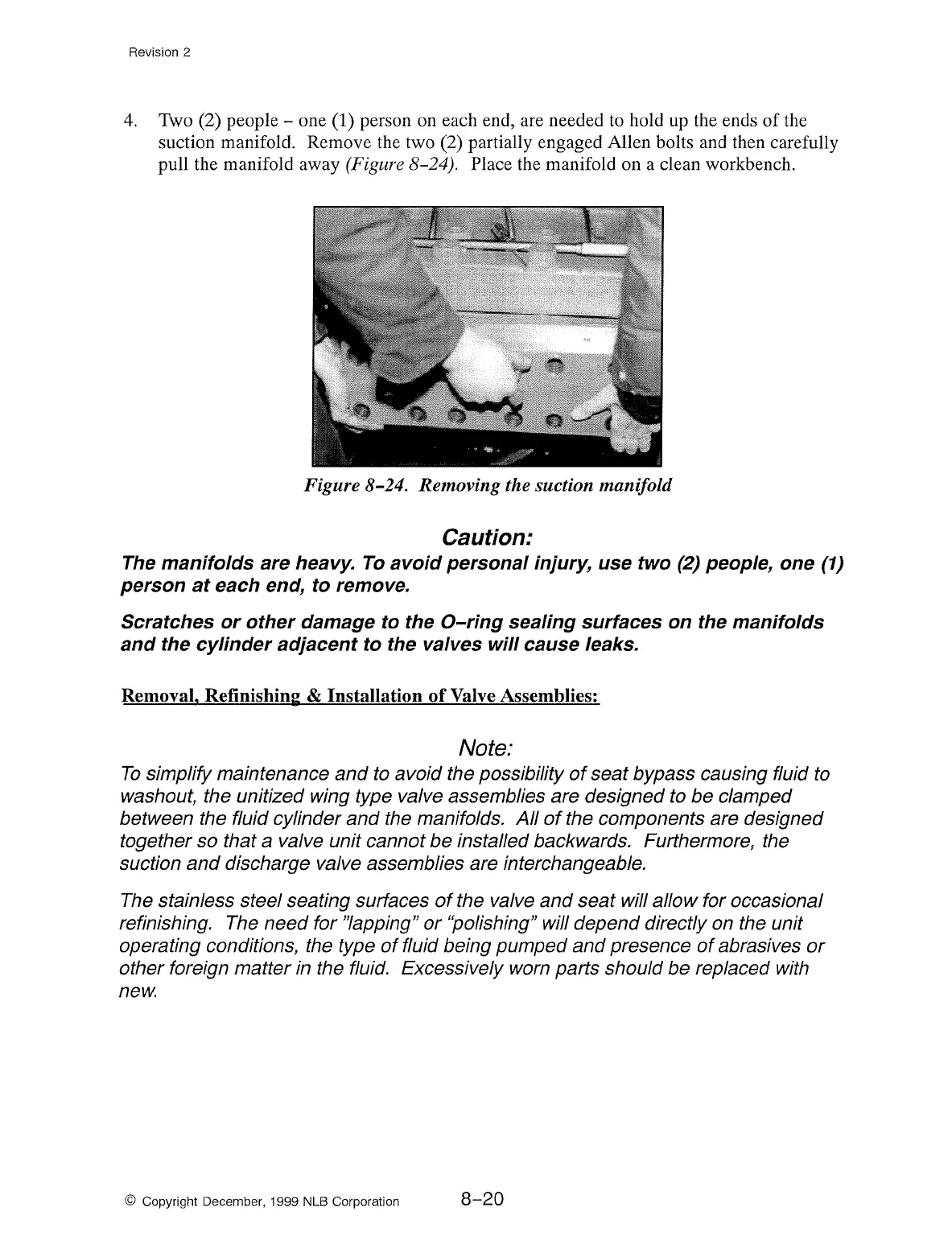
Two (2) people - one (1) person on each end, are needed to hold up the ends
of
the
suction manifold. Remove the two (2) partially engaged Allen bolts and then carefully
pull the manifold away
(Figure 8-24). Place the manifold on a clean workbench.
Figure 8-24. Removing the suction manifold
Caution:
The
manifolds are heavy.
To
avoid personal injury, use two
(2)
people, one
(1)
person
at
each end,
to
remove.
Scratches
or
other damage
to
the
0-ring
sealing surfaces on the manifolds
and the cylinder adjacent
to
the valves will cause leaks.
Removal, Refinishing & Installation
of
Valve Assemblies:
Note:
To
simplify maintenance and to avoid the possibility
of
seat bypass causing fluid to
washout, the unitized wing type valve assemblies are designed to be clamped
between the fluid cylinder
and
the manifolds.
All
of
the components are designed
together so that a valve unit cannot
be
installed backwards. Furthermore, the
suction
and
discharge valve assemblies are interchangeable.
The
stainless steel seating surfaces
of
the valve and seat will allow for occasional
refinishing. The need for
"lapping"
or
"polishing" will depend directly on the unit
operating conditions, the type
of
fluid being pumped and presence
of
abrasives
or
other foreign matter in the fluid. Excessively worn parts should be replaced with
new.
© Copyright December, 1999 NLB Corporation
8-20