Revision 2
5.
After the manifolds have been removed
to
a clean workbench, the valves are exposed.
Lift or pull the valve assemblies from the main fluid cylinder by hand
(Figure 8-25).
Figure 8-25. Removing the valve assemblies.
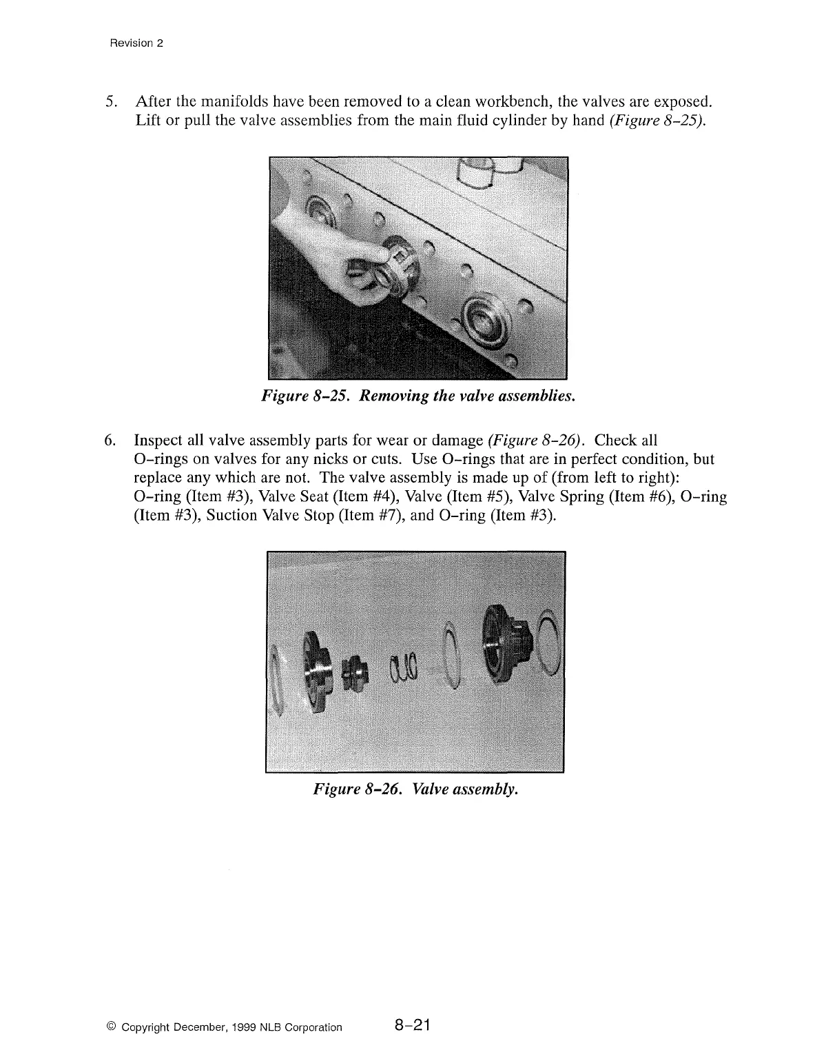
6.
Inspect all valve assembly parts for wear or damage (Figure 8-26). Check all
0-rings
on valves for any nicks or cuts. Use
0-rings
that are in perfect condition, but
replace any which are not. The valve assembly is made up of (from left
to
right):
0-ring
(Item #3), Valve Seat (Item #4), Valve (Item #5), Valve Spring (Item #6),
0-ring
(Item #3), Suction Valve Stop (Item #7), and
0-ring
(Item #3).
Figure 8-26.
Valve
assembly.
© Copyright December, 1999 NLB Corporation
8-21