Revision 6
C.
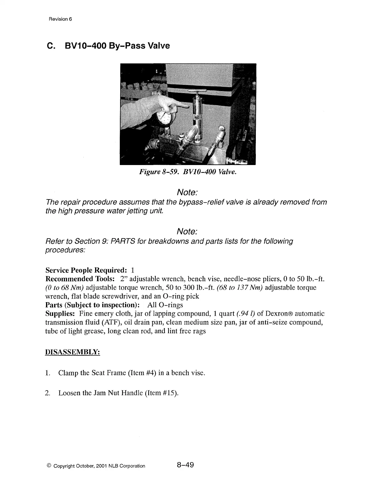
BV10-400 By-Pass Valve
Figure 8-59. BVJ0-400
Valve.
Note:
The
repair procedure assumes that the bypass-relief valve is already removed from
the high pressure water jetting unit.
Note:
Refer
to
Section 9: PARTS for breakdowns
and
parts lists for the following
procedures:
Service People Required: 1
Recommended Tools:
2" adjustable wrench, bench vise, needle-nose pliers, 0
to
50 lb.-ft.
(0
to
68 Nm) adjustable torque wrench, 50 to 300 lb.-ft. (68
to
137 Nm) adjustable torque
wrench, flat blade screwdriver, and an
0-ring
pick
Parts
(Subject to inspection): All
0-rings
Supplies: Fine emery cloth, jar of lapping compound, 1 quart (.94 l) of Dexron® automatic
transmission fluid (ATF), oil drain pan, clean medium size pan, jar
of
anti-seize compound,
tube
of
light grease, long clean rod, and lint free rags
DISASSEMBLY:
1.
Clamp the Seat Frame (Item #4) in a bench vise.
2.
Loosen the Jam Nut Handle (Item #15).
© Copyright October,
2001
NLB Corporation
8-49