2 Installing the Nokia IP390 Appliance
28 IP390 Security Platform Installation Guide
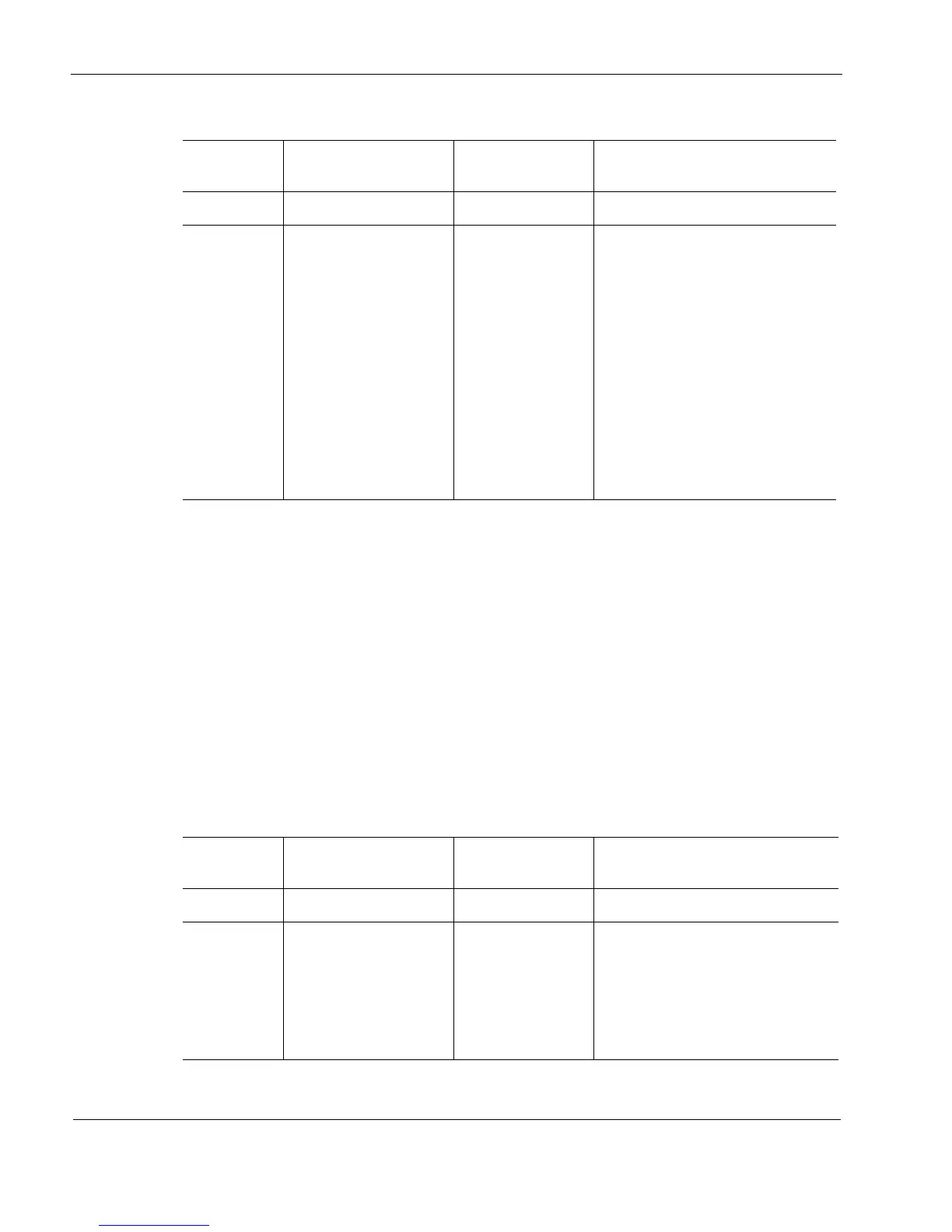
Table 6 Pin Assignments Console Connector and Cable
The console cable provided with the IP390 is comprised of two parts:
6-foot rollover cable with RJ-45 terminations
RJ-45 to DB-9 adapter
On the opposite end of the console cable, connect the RJ-45 to the DB-9 adapter, which you can
then connect to the host terminal.
Auxiliary Port
Use the built-in serial (AUX) port, shown in Figure 1, to establish a modem connection for
managing the appliance remotely or out-of-band. The default configuration of the serial ports
are: 9600 baud, 8 bits, no parity, and 1 stop. bit. Table 7 provides pin assignment information for
modem connections.
Table 7 Pin Assignments for AUX Connector and Modem Cable
Console Port
(DTE)
RJ-45 to RJ-45 Rollover
Cable
RJ-45 to DB-9
Terminal Adapter Remote Device
Signal RJ-45 Pin RJ-45 Pin DB-9 Pin Signal
RTS 1 8 8 CTS
DTR 2 7 6 DSR
TxD 3 6 2 RxD
GND 4 5 5 GND
GND 5 4 5 GND
RxD 6 3 3 TxD
DSR 7 2 4 DTR
CTS 8 1 7 RTS
Auxiliary
Port (DTE)
RJ-45 to RJ-45 Rollover
Cable
RJ-45 to DB-25
Modem Adapter
Modem
Signal RJ-45 Pin RJ-45 Pin DB-25 Pin Signal
RTS 1 8 4 RTS
DTR 2 7 20 DTR
TxD 3 6 3 TxD
GND 4 5 7 GND