4 About IP390 Appliance Network Interface Cards
46 IP390 Security Platform Installation Guide
Caution
Remove the T1 cable before working on any Nokia appliance.
Caution
Nokia requires that this equipment be installed by authorized, experienced service
personnel who have the equipment installation instructions. Nokia requires that all
equipment be connected to a power source using a socket-outlet with protective
earthing connection.
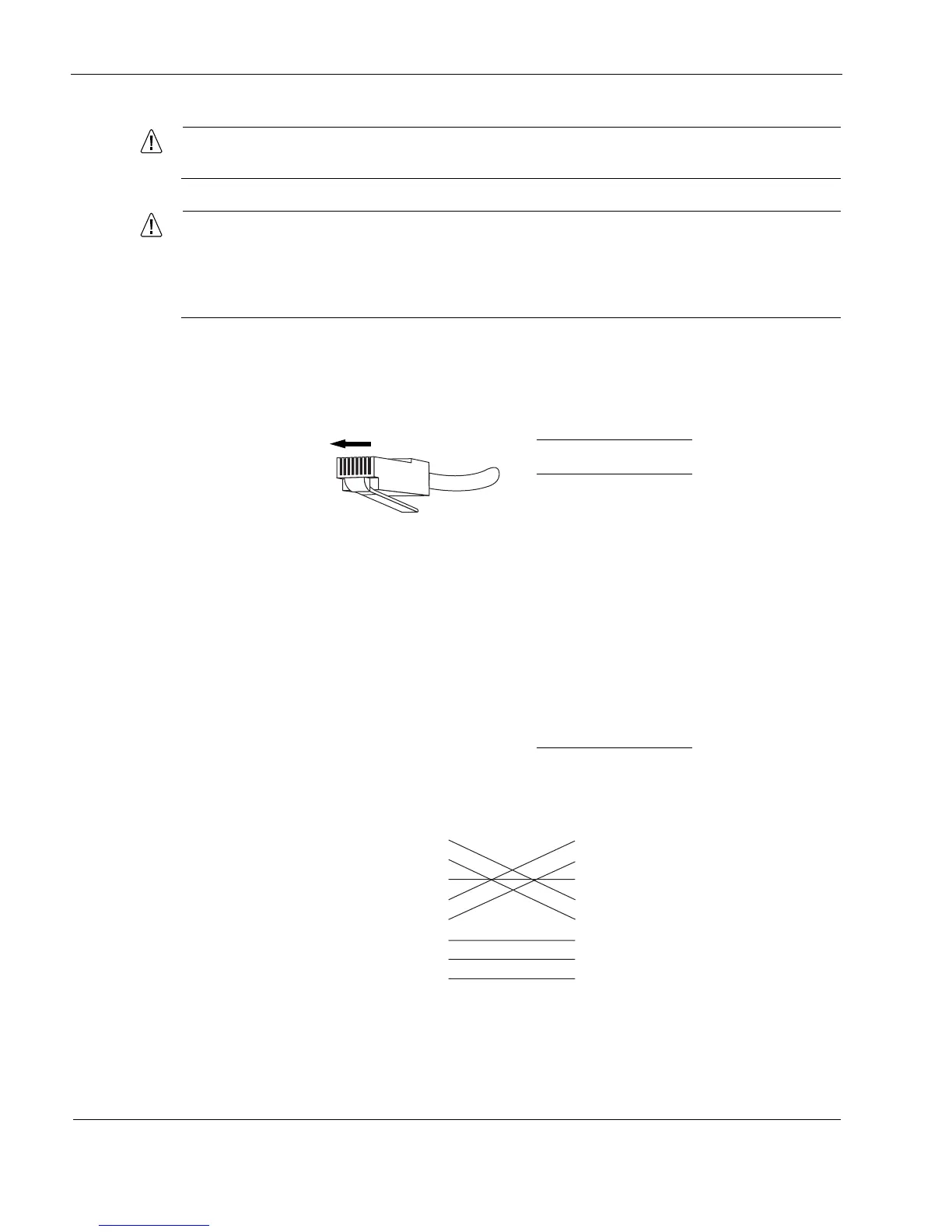
In the following figure, the RJ-48 connector is numbered from right to left, with the copper pins
facing up and toward you.
Figure 19 T1 Network Interface Card Receptacle and Pin Assignments
In the following figure, wiring is shown for a T1 crossover cable.
Figure 20 T1 Crossover Cable Pin Connections
Pin# Assignment
1
RX
2
RX
3
4
TX
5
TX
6
7
8
8 1
00270
1
2
3
4
5
6
7
8
1
2
3
4
5
6
7
8
00018.1