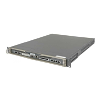
Nokia IP560 Security Platform Overview
IP560 Security Platform Installation Guide 27
Figure 4 Pin Assignments for Auxiliary Connector and Modem Cable
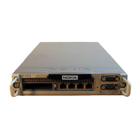
System Status LEDs
You can visually monitor the status of the IP560 security platform by
checking the system status LEDs. The system status LEDs are located on the
center of the front panel, as shown in Figure 5.
Auxiliary Port
(DTE)
RJ-45 to RJ-45 Rollover
Cable
RJ-45 to DB-25
Modem Adapter Modem
Signal RJ-45 Pin RJ-45 Pin DB-25 Pin Signal
RTS 1 8 4 RTS
DTR 2 7 20 DTR
TxD 3 6 3 TxD
GND 4 5 7 GND
GND 5 4 7 GND
RxD 6 3 2 RxD
DSR 7 2 8 DCD
CTS 8 1 5 CTS