IP560 Security Platform Installation Guide 9
List of Figures
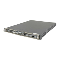
Figure 1 Component Locations Front View . . . . . . . . . . . . . . . . . 23
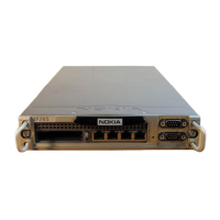
Figure 2 Four-Port 10/100/1000 Ethernet PMC Details . . . . . . . 24
Figure 3 Pin Assignments for Console Connector and Console
Cable . . . . . . . . . . . . . . . . . . . . . . . . . . . . . . . . . . . . . 25
Figure 4 Pin Assignments for Auxiliary Connector and Modem
Cable . . . . . . . . . . . . . . . . . . . . . . . . . . . . . . . . . . . . . 27
Figure 5 Nokia IP560 Security Platform System Status LEDs . . 28
Figure 6 Location of the PCMCIA PC Card Slot . . . . . . . . . . . . . 30
Figure 7 Power Supply and Fan Unit Locations . . . . . . . . . . . . . 31
Figure 8 Power Supply, Cooling Fan, and Power Switch
Locations . . . . . . . . . . . . . . . . . . . . . . . . . . . . . . . . . . 31
Figure 9 Fan Unit . . . . . . . . . . . . . . . . . . . . . . . . . . . . . . . . . . . . . 33
Figure 10 Rack-Mounting Screw Locations . . . . . . . . . . . . . . . . . 38
Figure 11 Power Switch Location . . . . . . . . . . . . . . . . . . . . . . . . 47
Figure 12 Nokia Network Voyager Reference Access Points
Example . . . . . . . . . . . . . . . . . . . . . . . . . . . . . . . . . . . 53
Figure 13 Four-Port 10/100 Ethernet NIC Front Panel Details . . 69
Figure 14 Output Connector for the Ethernet Cable . . . . . . . . . . 70
Figure 15 Ethernet Crossover-Cable Pin Connections . . . . . . . . 71
Figure 16 Four-Port Copper Gigabit Ethernet NIC Front Panel
Details . . . . . . . . . . . . . . . . . . . . . . . . . . . . . . . . . . . . 72
Figure 17 Two-Port Copper Gigabit Ethernet NIC Front Panel
Details . . . . . . . . . . . . . . . . . . . . . . . . . . . . . . . . . . . . 73