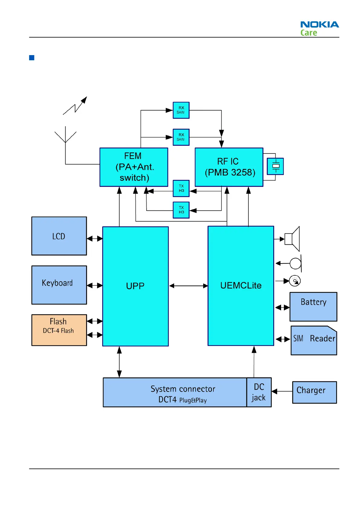
System module block diagram
The main board consists of a radio frequency part and a baseband part. The User Interface parts are situated
at the UI side. The 2VJ is the engine module of the mobile device.
Figure 110 Module block diagram
RM-512; RM-513; RM-514; RM-515; RM-543
System Module
Issue 2 COMPANY CONFIDENTIAL Page 6 –5
Copyright © 2009 Nokia. All rights reserved.