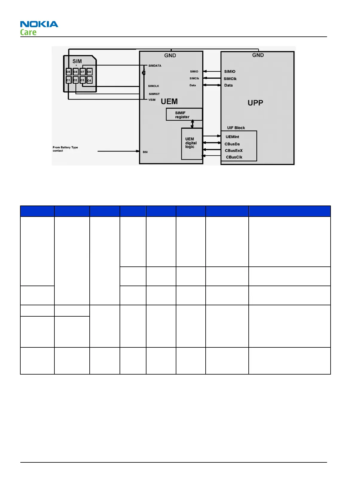
Figure 116 SIM interface block diagram
External signals and connections
Table 11 System connector
Signal From To Min Nom Max Condi-tion Note
XMICP HS/HF Mic Liteplu
s
2/60m
V diff
Analog
audio in
Headset Mic bias and
audio signal 2mV
nominal. HF Mic signal
60mV nominal.
Differential symmetric
input.
DC bias
2V2kohm
Accessory detection by
bias loading
XMICN 2/60m
V diff
Ana in / 1k
to GND
Hook interrupt by heavy
bias loading
XEARP HS/HF Liteplu
s
100 mV
diff
Ana in Quasi-differential DC-
coupled earpiece/HF
amplifier signal to
accessory. DC biased to
0.8V
XEARN EAR/
Amp.
INT
HEADINT
Switch Liteplu
s
0/2.7V Dig in HS interrupt from bottom
connector switch when
plug inserted.
RM-512; RM-513; RM-514; RM-515; RM-543
System Module
Page 6 –16 COMPANY CONFIDENTIAL Issue 2
Copyright © 2009 Nokia. All rights reserved.