SIM interface
The Liteplus contains the SIM interface logic level shifting. The SIM interface can be programmed to support
3V and 1.8V SIMs. SIM supply voltage is selected by with register in the Liteplus. It is only allowed to change
the SIM supply voltage when the SIM IF is powered down.
The SIM power up/down sequence is generated in the Liteplus. This means that the Liteplus generates the
RST signal to the SIM. In addition, the SIMCardDet signal is connected to Liteplus. The detection is taken from
the BSI signal, which detects the removal of the battery. The monitoring of the BSI signal is done by a
comparator inside Liteplus. The comparator offset is such that the comparator outputs do not alter state as
long as the battery is connected. The threshold voltage is calculated from the battery size specifications.
The SIM interface is powered up when the SIMCardDet signal indicates ”card in”. This signal is derived from
the BSI signal.
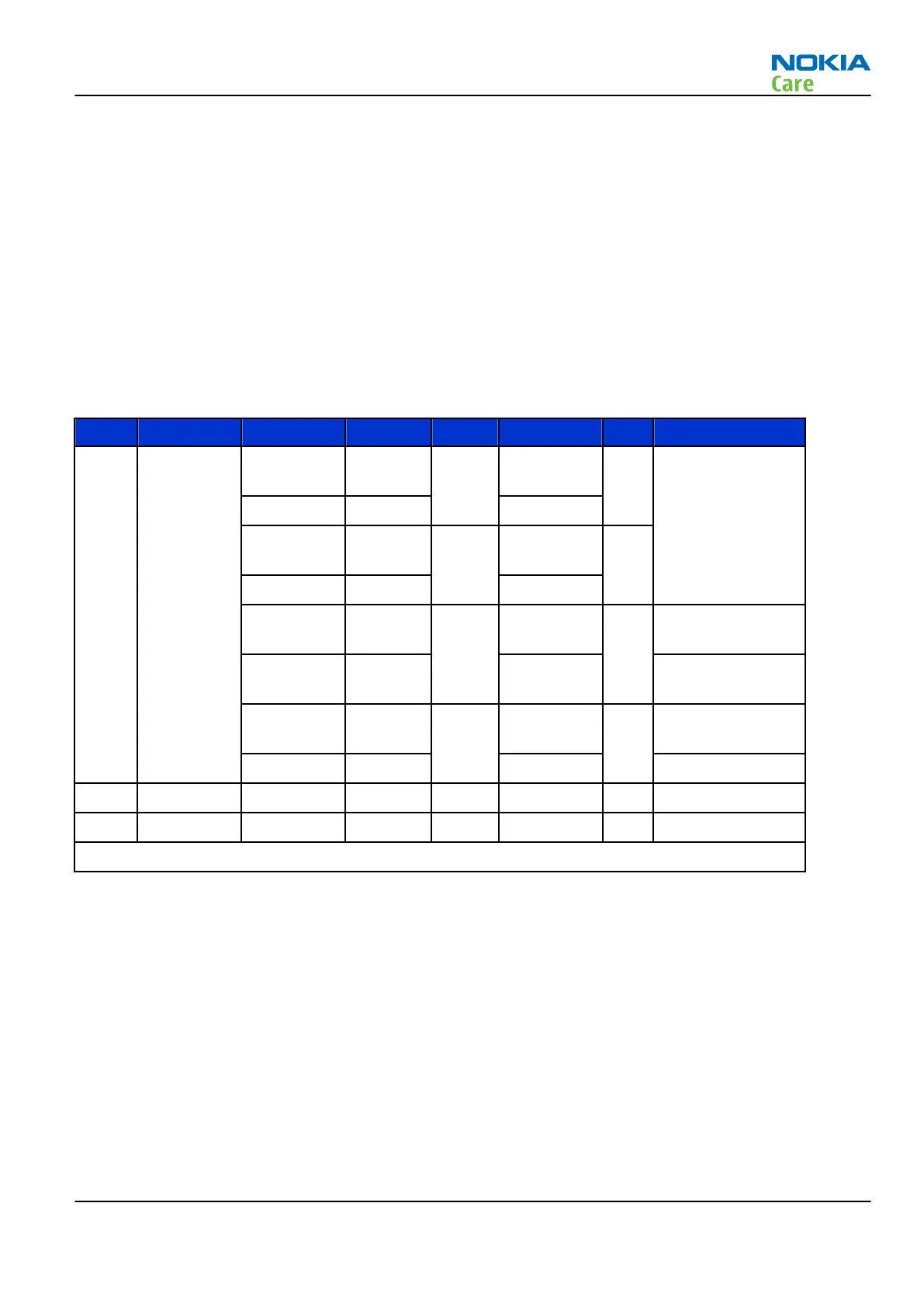
Table 10 SIM interface
Pin Name Parameter Min Typ Max Unit Notes
4 DATA 1.8V Voh 0.9xVSI
M
VSIM V SIM data (output)
1.8V Vol 0 0.15xVSIM
3V Voh 0.9xVSI
M
VSIM
3V Vol 0 0.15xVSIM
1.8V Vih 0.7xVSI
M
VSIM V SIM data (input)
1.8V Vil 0 0.15xVSIM Trise/Tfall max
1us
3V Vil 0.7xVSI
M
VSIM
3V Vil 0 0.15xVSIM
5 NC Not connected
6 GND GND 0 0 V Ground
VSIM specified in regulator section in this document
RM-512; RM-513; RM-514; RM-515; RM-543
System Module
Issue 2 COMPANY CONFIDENTIAL Page 6 –15
Copyright © 2009 Nokia. All rights reserved.