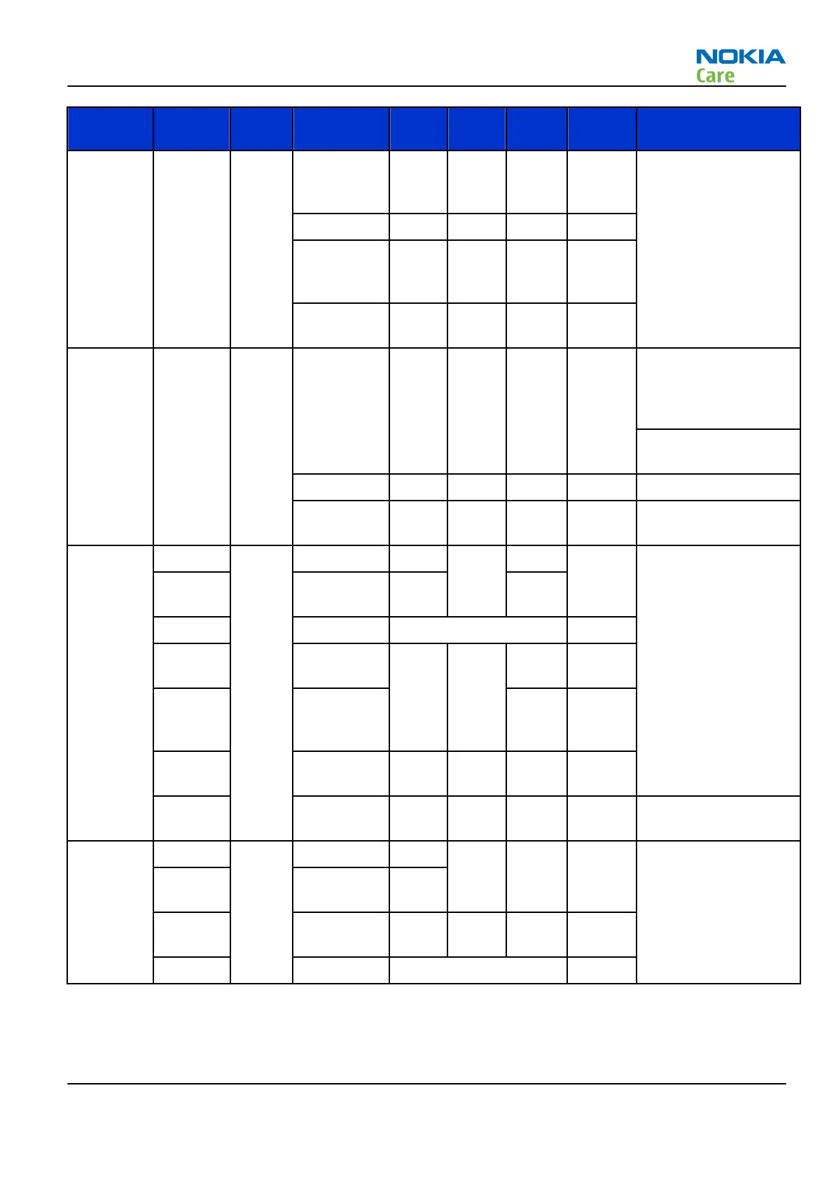
Signal
name
From To Parameter Min Typ Max Unit Function
RXIP,
RXIN,
RXQP,
RXQN
RF-IC Litepl
us
Voltage
swing
(static)
1.4 1.45 Vpp Differential positive /
negative in-phase
and quadrature Rx
Signals.
DC level 1.3 1.35 1.4 V
I/Q
amplitude
mismatch
0.2 dB
I/Q phase
mismatch
-0.5 0.5 deg
TXIP,
TXIN,
TXQP,
TXQN
Liteplus RF-IC Differential
voltage
swing
(static)
2.25 2.45 Vpp Differential positive /
negative in-phase
and quadrature Tx
Signals
In High-Z when RX is
receiving.
DC level 1.17 1.20 1.23 V
Source
Impedance
200 W
AFC Liteplus VCTCX
O
Voltage Min 0.0 0.1 V Automatic Frequency
Control signal for
VCTCXO
Programmable
(AFCOUT
)
Max 2.4 2.55
Resolution 11 bits
Load
resistance
1 kW
and
capacitanc
e
100 nF
Source
Impedance
200 W
Output
impedance
10 MW Path powered down
TxC Liteplus RF-IC Voltage Min 0.1 V Transmitter power
level and ramping
control, Ref Liteplus
RF converter
specification
(AUXOUT
)
Max 2.4
Source
Impedance
200 W
Resolution 10 bits
RM-512; RM-513; RM-514; RM-515; RM-543
System Module
Issue 2 COMPANY CONFIDENTIAL Page 6 –13
Copyright © 2009 Nokia. All rights reserved.