NORDAC FLEX (SK 200E ... SK 235E) – Brief instructions for Frequency Inverters
30 BU 0240 en-US-4920
The capacity of the SK BRI4 is limited (see also the following note field) and can be calculated as
follows.
=
1 +
(
30/
)
but the following applies P < P
max
(P=braking power (W), P
n
= continuous braking power of resistor (W), P
max
. peak braking power, t
brake
= duration of
braking process (s))
The permissible continuous braking power P
n
must not be exceeded on average in the long-term.
Pos: 106 /A nleit ung en/El ek tr onik /FU und Star ter /2. M ontag e u nd I nst alla tio n/Z ube hör/ Brem swi der st and/ SK 1x 0E , SK 2xx E/In ter ner Br emsw id erst and SK BR I4- ... IN FORM ATION Spitze nlas t begre nzen - DIP-Sc halter (S1) [S K 2xxE] @ 21 \mod_1528365369602_14638.docx @ 2424735 @ @ 1
Peak load limitation - DIP switch (S1)
Switch the DIP switch (S1), DIP-No. 8 (please see chapter 4.2.2.2 "DIP switches (S1)")to "on" when using
internal braking resistors. This is important in order to activate a maximum output limit to protect the braking
resistor.
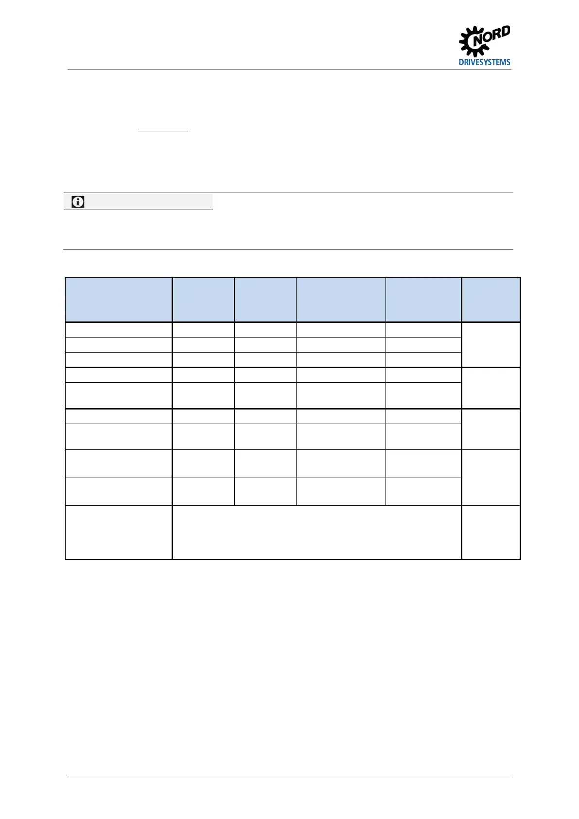
Pos: 107 /A nleit ung en/El ek tr onik /FU und Star ter /2. M ontag e u nd I nst alla tio n/Z ube hör/ Brem swi der st and/ SK 1x 0E , SK 2xx E/El ek tris che Da ten ( BR I) [ SK 2x xE ] @ 21\mod_1528374732538_14638.docx @ 2424884 @ 5 @ 1
Electrical data
Designation
(IP54)
Mat. No. Resistor Max. continuous
output/limit
2)
(P
n
)
Power
consumption
1)
(P
max
)
Connecting
cable or
terminals
SK BRI4-1-100-100 275272005
100 Ω
100 W/25% 1.0 kWs
Silicone flexible
lead
2x AWG 20
approx. 60 mm
Ω
400 Ω
SK BRI4-2-100-200 275272105
100 Ω
200 W/25% 2.0 kWs
lead
2x AWG 18
approx. 60 mm
SK BRI4-2-200-200 275272108
200 Ω
200 W/25% 2.0 kWs
Ω
lead
2x AWG 16
approx. 170 mm
SK BRI4-3-100-300 275272205
100 Ω
300 W/25% 3.0 kWs
SK BRI4-3-023-600 275272800
3)
23 Ω
(2 x 47 Ω)
600 W/25%
(2 x 300 W)
6.0 kWs
(2 x 3 kWs)
Silicone flexible
lead
2x 2x AWG 16
approx. 170 mm
SK BRI4-3-050-600 275272801
3)
50 Ω
(2 x 100 Ω)
600 W/25%
(2 x 300 W)
6.0 kWs
(2 x 3 kWs)
DIP switch (S1),
DIP-No. 8 = on
Maximum once within 10 s
2)
In order to prevent inadmissible heating of the connection unit, the continuous power is
limited to 1/4 of the rated power of the braking resistor.
This also has a limiting effect on energy consumption.
Set consisting of 2 resistors to be connected in parallel
Pos: 10 8 /Allg emein/ Allg emeing ültig e Mod ule/---------Sei tenum bruc h k omp akt --------- @ 13\mod_1476369695906_0.docx @ 2265496 @ @ 1
 Loading...


