Installation
3-2
Part 1618871−01
2020 Nordson Corporation
System Connections
Interconnect Cable Connections
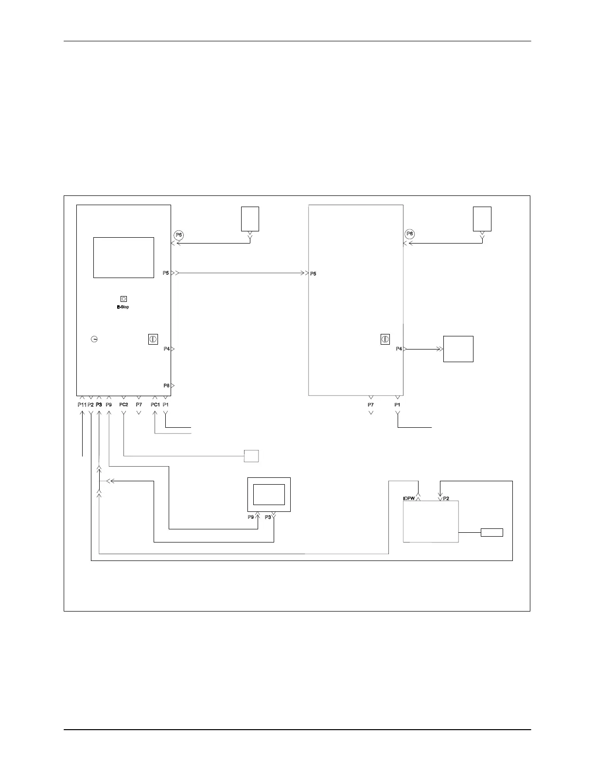
See Figure 3-1 and refer to Tables 3-1 and 3-2 for connection diagram and
cables for a typical system with 32 HD automatic spray guns, remote
controller, and part ID connections.
NOTE: For VT systems, the P6 connection is not applicable.
Main Controller
Auxiliary Controller
Remote Controller
Part ID
MECP
HD Pump Module HD Pump Module
Photo Eye
Encoder
MECP
Customer
MGI
if equipped
(see note)
NOTE: If system has auxiliary controller, MGI connection should be done at P4 location on auxiliary controller.
If only using a main controller, MGI connection should be done at P4 location on main controller.
Figure 3-1 Typical System Interconnect Cable Connections

 Loading...


