RetroFit Refill System with Nordson Level Sensor
A-6
Part 1121938_02
2013 Nordson Corporation
Configuration Switch
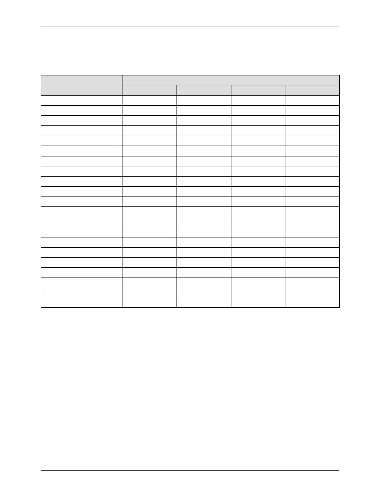
The configuration switches are used to set various system modes. Refer to
the following table for the configuration switch settings on your unit.
Melter Configuration Switch Settings
Switch 1 Switch 2 Switch 3 Switch 4
ProBlue 4 Integrated INTEGR INT TcA 150
ProBlue 7 Integrated INTEGR INT TcA 150
ProBlue 10 Integrated INTEGR INT TcB 150
ProBlue 4 Retrofit RETRO INT TcA 150
ProBlue 7 Retrofit RETRO INT TcA 150
ProBlue 10 Retrofit RETRO INT TcB 150
ProBlue 15, 30/50 RETRO INT TcB 150
Mesa 4 RETRO INT TcA 150
Mesa 6 RETRO INT TcA 150
Mesa 9 RETRO INT TcB 150
Mesa 14 RETRO INT TcB 150
Series 3100 RETRO INT TcA 150
Series 3400 RETRO INT TcA 150
Series 3500 RETRO INT TcB 150
Series 3700 RETRO INT TcB 150
Series 3860/3960 RETRO INT TcB 300
DuraBlue 10 RETRO INT TcB 150
DuraBlue 16 RETRO INT TcB 150
DuraBlue/VersaBlue 25 RETRO INT TcB 300
DuraBlue/VersaBlue 50 RETRO INT TcB 300
DuraBlue/VersaBlue 100 RETRO INT TcB 300
NOTE: Each board setting is configured to the specific melter at the factory.
NOTE: Switch 2 is used to select an external (EXT) external amplifier sensor
such as the level sensor used on previous Fulfill units.
 Loading...