Controls and Indicators
UDACT Instruction Manual PN 50050:H 09/16/2002 11
Controls and Indicators
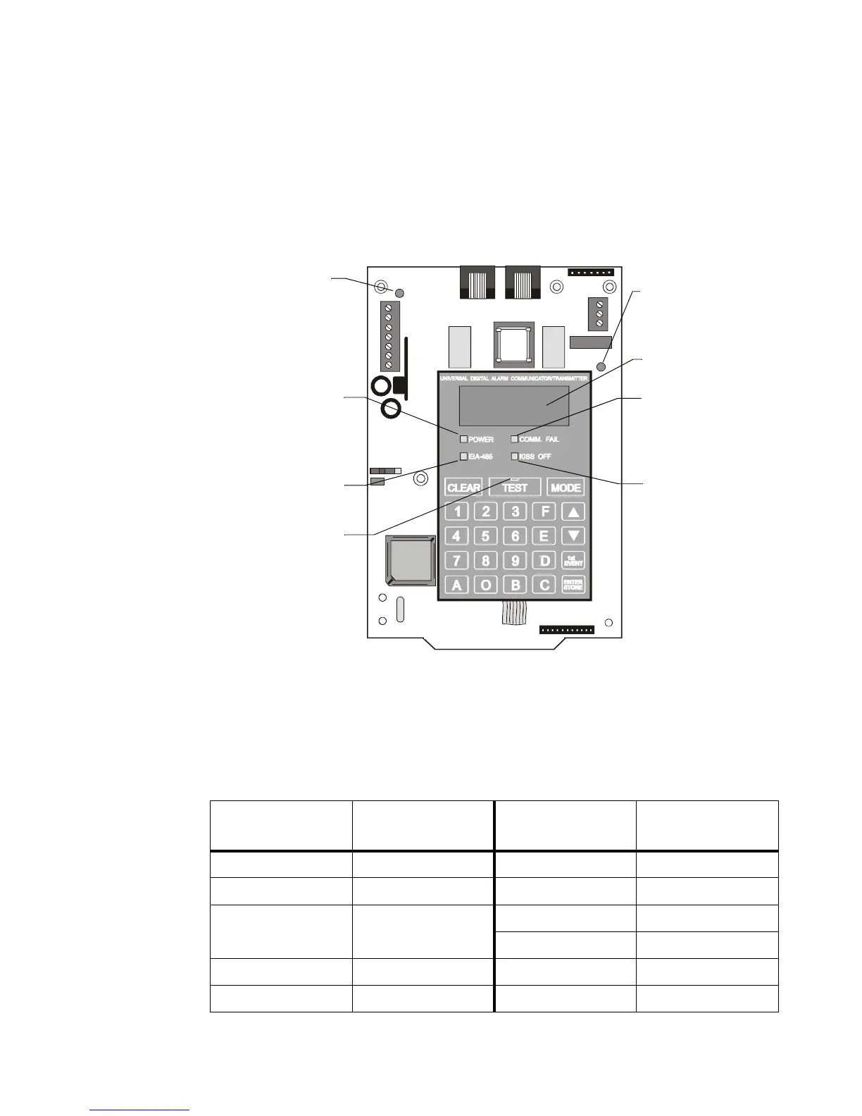
The following membrane type switches are provided on the front panel of the UDACT:
Displays are as shown below:
Figure 1 Controls and Indicators
Compatible Panels
The UDACT has been designed to be compatible with the following “Notifier” Fire Alarm Control Panels.
FACP firmware with the listed part numbers or higher (those part numbers beginning with a # are higher than
those without) must be installed to allow use of the UDACT with the corresponding panel.
Table 1 Compatible FACP & Firmware
CLEAR TEST MODE
Up Arrow Down Arrow Digits 0 - 9
1st EVENT ENTER/STORE Letters A -F
UDACT-01.cdr
COMM. FAIL
Yellow LED
KISS OFF
Green LED
EIA-485
Yellow LED
POWER
Green LED
Four, Seven
Segment Displays
Primary Active -
Red LED
(phone line)
Secondary Active -
Red LED
(phone line)
TEST
Green LED
Fire Alarm Control
Panel
FACP Firmware
Part Number
Fire Alarm Control
Panel
FACP Firmware
Part Number
System 500 73611 AFP-100 #AFP100V10
System 5000 73610 AFP-200 73609
AM2020/AFP1010 6.6 Standalone
M2.7 Network
AFP-300/AFP-400 #AFP4R20
NFS-640 #NFS6R1.00
INA M2.8 Network AFC-600 #AFC6R10
NCA #NCAV1.0 NFS-3030 #3030V1.00
Technical Manuals Online! - http://www.tech-man.com