UDACT Instruction Manual PN 50050:H 09/16/2002 67
Appendix A: AFP-100
General
The UDACT is capable of reporting a maximum of 56 zones or 198 points when used with the
AFP-100. For more information on the AFP-100 see the AFP-100 Instruction Manual.
Mounting
Internal
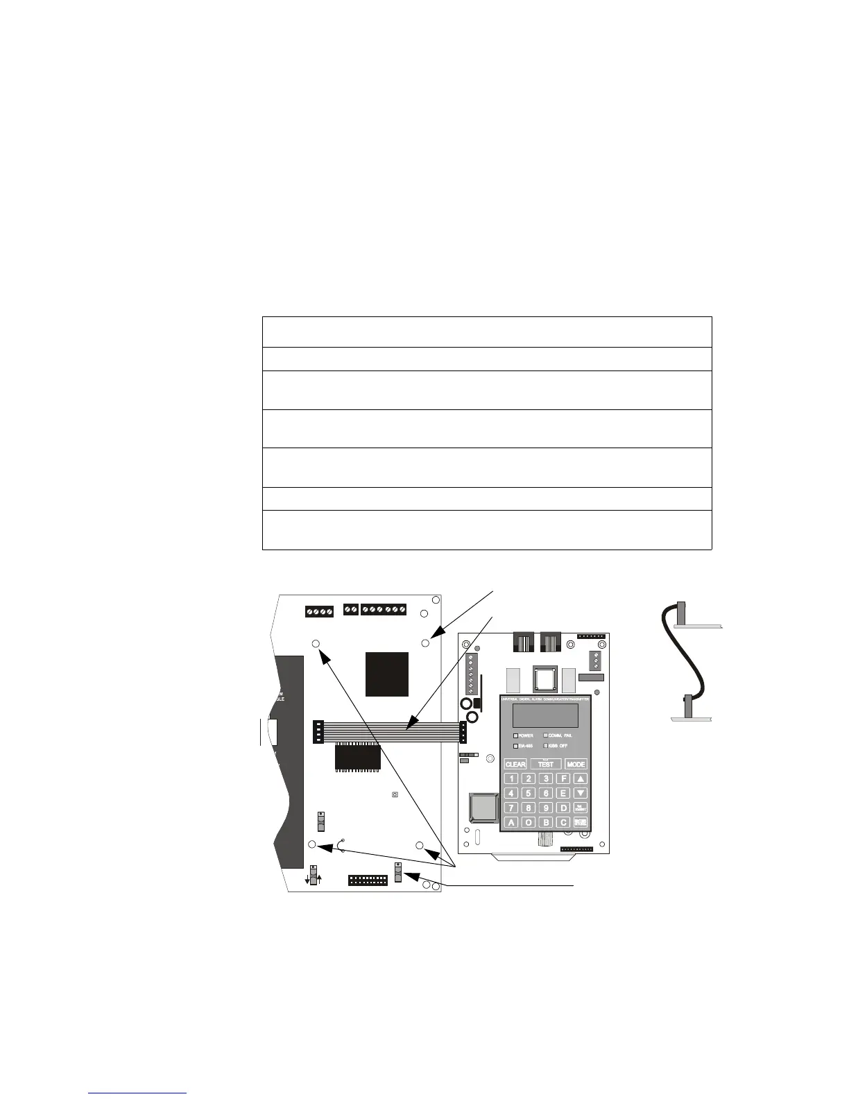
The UDACT can be mounted in the AFP-100 cabinet by following the instructions and referring to the
figure below:
Figure 15 UDACT Installation in AFP-100 Cabinet
Remote
The UDACT can also be mounted remotely using an ABS-8R or UBS-1 enclosure placed within 6000
feet (1828.8 meters) of the control panel.
Refer to "Remote Installation" on page 22 for installation instructions.
Step Action
1 Disconnect all sources of power (AC and DC).
2 Install 3 nylon and 1 aluminum 5/8” long snap-in standoffs (provided) in the
holes located on the right side of the circuit board.
3 Place the SW2 switch in the down position to enable AC Loss Delay
Reporting.
4 Carefully connect the ribbon cable (PN 75306, provided) to connector J16 on
the circuit board and to connector J10 on the UDACT.
5 Align and snap the UDACT to the nylon standoffs.
6 Secure the UDACT to the aluminum standoff using the screw provided.
Tighten securely.
J10
PC/PRINTER
TERM COMM
TROUBLE
RS-232
PC/PRINTER
RS-485
TERM. MODE
A B B+ A+ B- A-
1 COMM 2
ACS
SHIELD SLC SLC
OUT+ IN+ OUT- IN-
T
B
7
T
B
5
T
B
6
J16
J6
JP4
SW1
SW3
SW2
GNDFAULT
UDACT-20.cdr
NYLON Standoffs
ALUMINUM Standoff
UDACT
AFP-100
Ribbon Cable attached
as illustrated at right
SW2 Switch
Technical Manuals Online! - http://www.tech-man.com