Normal Mode
UDACT Instruction Manual PN 50050:H 09/16/2002 51
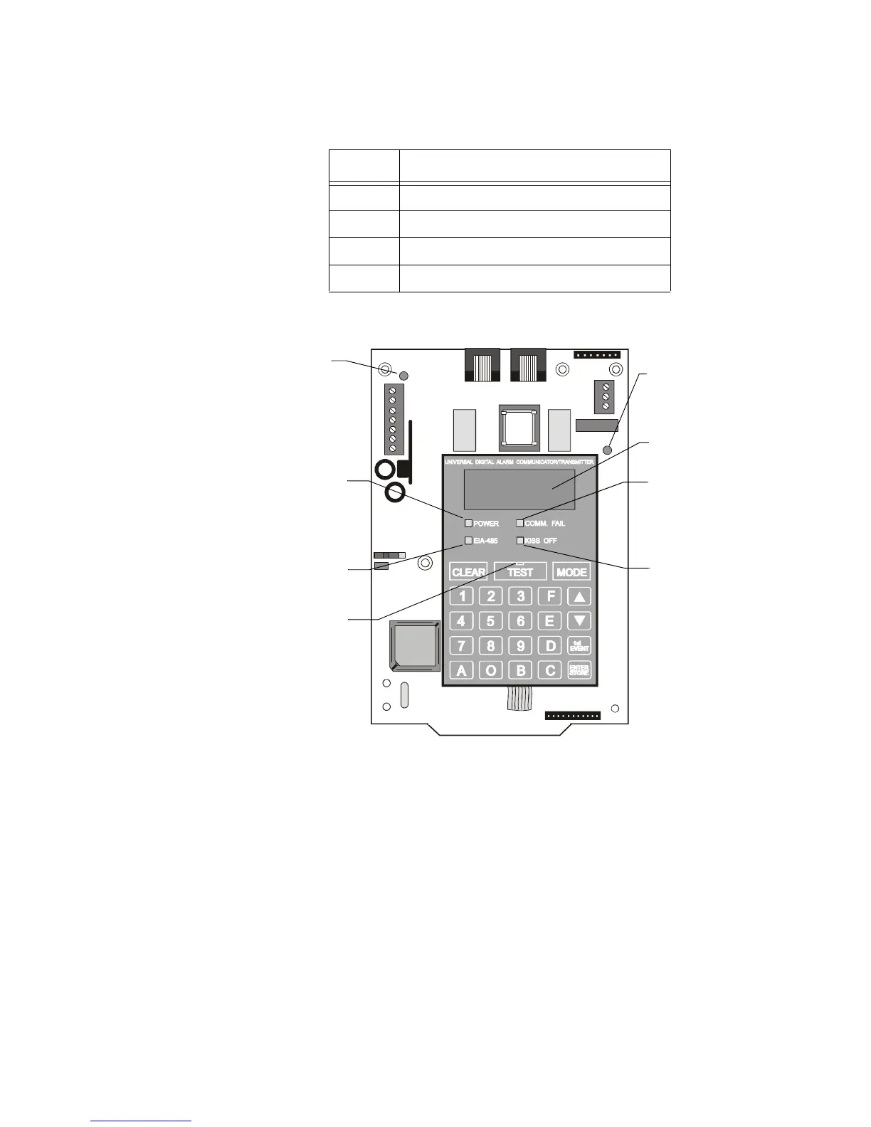
Displays and LEDs
Four, seven-segment red LED characters (see below) provide visual annunciation of UDACT trouble
conditions. A list of messages that may appear on the display in Normal Mode is shown below:
Table 10 Normal Mode Messages
Seven individual LEDs are provided on the panel as described and shown below:
Figure 13 Display and LEDs
EIA-485 - A yellow LED that turns on steady when a fault on the EIA-485 circuit is detected.
Comm. Fail - This yellow LED turns on to indicate the loss of both telephone lines or that the
maximum number of attempts to communicate with both Central Stations has been unsuccessful. Note:
During a comm fail, the display will show either a PH1 and PH2 or no1 and no2.
Power - A green LED that remains on while power is supplied to the UDACT. If this indicator fails to
light under normal conditions, service the system immediately.
Kiss Off - A green LED that blinks when the Central Station has acknowledged receipt of each
transmitted message.
Test - A green LED that turns on to indicate that a manual test message is being transmitted and turns
off after messages transmit.
Primary Line Active - A red LED that indicates the primary phone line is active.
Secondary Line Active - A red LED that indicates the secondary phone line is active.
Message Meaning
PH_1 Primary Number Communication Fault
PH_2 Secondary Number Communication Fault
no_1 Primary Phone Line Fault
no_2 Secondary Phone Line Fault
UDACT-01.cdr
COMM. FAIL
Yellow LED
KISS OFF
Green LED
EIA-485
Yellow LED
POWER
Green LED
Four, Seven
Segment Displays
Primary Active -
Red LED
(phone line)
Secondary Active -
Red LED
(phone line)
TEST
Green LED
Technical Manuals Online! - http://www.tech-man.com