Wiring
68
UDACT Instruction Manual PN 50050:H 09/16/2002
Wiring
CAUTION: Remove all power from the control panel by disconnecting AC and batteries before
making any connections to prevent personal and/or circuit damage.
Connections
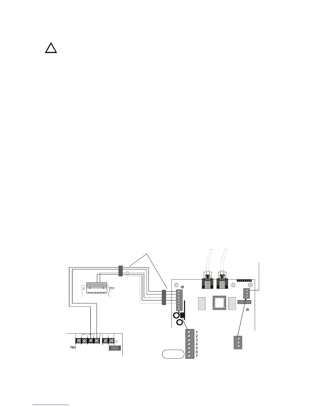
With internal installation the EIA-485 circuit and 24VDC are provided directly from the J16 connector.
Note: A 120 ohm EOL resistor is not required on the UDACT EIA-485 terminals when it is installed inside the AFP-100
cabinet.
For external connections refer to Figure 16 on page 68.
Connect the communication line between the EIA-485 terminal block TB5 on the AFP-100 and TB-1
terminals 3 and 4 on the UDACT, being certain to observe polarity.
If last device or no other devices are connected to the external EIA-485, install a 120 ohm EOL resistor
(PN 71244) across UDACT TB1 terminals 3 and 4.
Connect the
Ground Wire (PN 71073, provided) from the UDACT EARTH terminal on TB3 to a solid
building earth ground.
Connect 24VDC filtered, non-resettable power from terminal block TB4 on the AFP-100 to TB1
terminals 1 and 2 on the UDACT.
Notes:
1. Ferrite cores, PN 29090, are recommended for all applications.
2. Recommended wire is 12 AWG (3.25mm
2
) to 18 AWG (0.75mm
2
), twisted pair, shielded cable.
Connect only one end of shield: a) shield may be connected to cabinet (earth ground) at fire alarm
panel, or b) shield may be connected to TB1 Terminal 5 (Shield) at UDACT as shown in Figure 16.
Note: The shield end that is not connected should be insulated to prevent accidental grounding. Do not connect both
ends of shield under any circumstance since a ground fault may result.
3. Conduit is recommended for external wire runs. Consult local building codes.
4. Refer to "Specifications" on page 13 for power requirements.
Below is a remote installation of a UDACT with an AFP-100:
Figure 16 UDACT and AFP-100
!
EARTH
Comm FAILURE
+24V
+24V
GND
RS+
RS–
SHIELD
RS+
Rs–
ACS/TERM
TERM
COMMONCOMMON
BATT -
+24V POWER+24V RESET
BATT +
UDACT-19.cdr
Solid Earth
Ground
Connection
To Phone Lines
(supervised)
DO NOT USE
AFP-100 Cabinet
AFP-100 Circuit Board
ABS-8R or UBS-1
Ferrite Core
Technical Manuals Online! - http://www.tech-man.com