Wiring
122
UDACT Instruction Manual PN 50050:H 09/16/2002
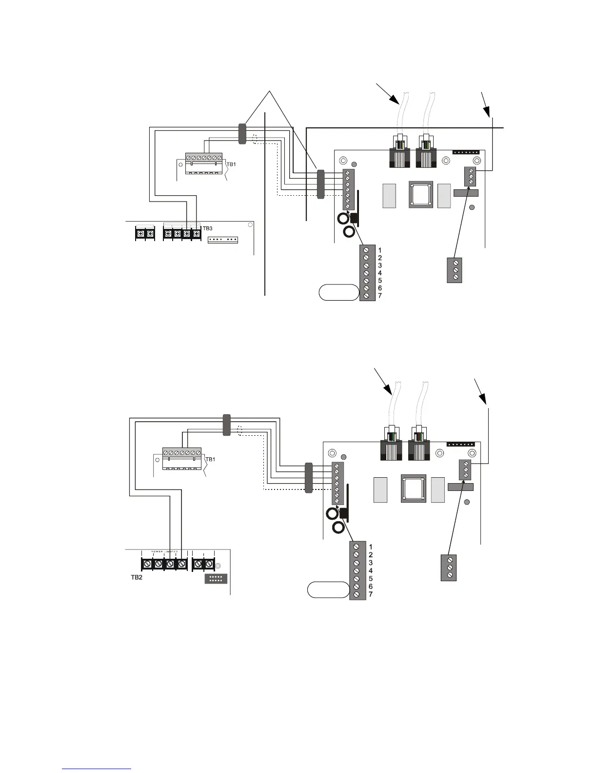
Below is a remote installation of a UDACT with an INA with an MPS-24A main power supply:
Figure 33 UDACT and INA with MPS-24A
Below is an internal installation of a UDACT with an INA and MPS-24B main power supply:
Figure 34 UDACT and INA with MPS-24B
EARTH
Comm FAILURE
+24V
+24V
GND
RS+
RS–
SHIELD
RS+
Rs–
ACS/TERM
TERM
+24R COMM ON +24
COM MON
POWER LI MITED
BAT + B AT -
To Phone Lines
(supervised)
Solid Earth
Ground
Connection
MPS-24A
INA
DO NOT USE
UDACT-17.cdr
INA Cabinet
ABS-8R or UBS-1
Ferrite Cores
EARTH
Comm FAILURE
+24V
+24V
GND
RS+
RS–
SHIELD
RS+
Rs–
ACS/TERM
TERM
COMMONCOMMON
BATT -
+24V POW ER+24V RESET
BATT +
To Phone Lines
(supervised)
Connect to CHS-4
Chassis
MPS-24B
INA
DO NOT USE
UDACT-18.cdr
Technical Manuals Online! - http://www.tech-man.com