Installation Circuit Connections
46 XPIQ PN 51013:C 7/01/03
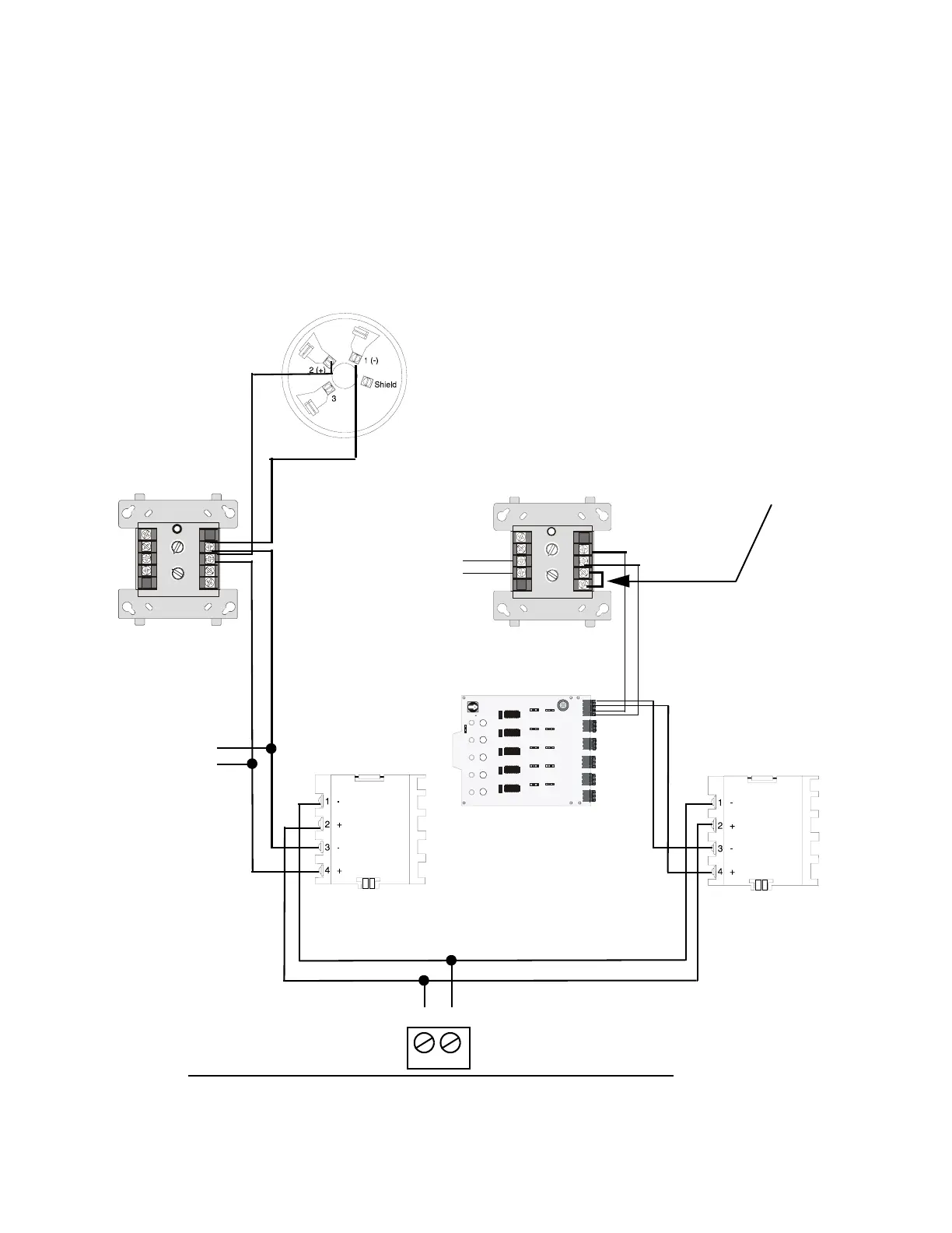
Wiring the Local SLC Branch for Degraded Mode Operation
The XPIQ-SLI terminal block TB2 provides a connection for local addressable initiating devices.
Wiring is connected only as Style 4 (Class B) with T-tapping allowed. The local devices are
powered by the SLC as long as communication is established. If SLC communication is lost, the
XPIQ-SLI switches to degraded mode providing power and direct monitoring of the local devices.
If a local device alarms during stand-alone mode, a local evacuation signal from a tone generator
will be sent to all speaker zones on the XPIQ. Devices do not latch in degraded mode, therefore
clearing the initiating device will also reset the alarm.
8
9
8
8
9
9
10
11
12
13
14
150
0
1
1
2
2
3
3
4
4
5
5
6
6
7
7
0
1
2
3
4
7
6
5
TENS
ONES
ADDRESS
LOOP
8
9
8
8
9
9
10
11
12
13
14
150
0
1
1
2
2
3
3
4
4
5
5
6
6
7
7
0
1
2
3
4
7
6
5
TENS
ONES
DDRESS
LOOP
Enable
Ena bl e
Enable
Enable
SW102
SW1
SW2
Ba s e
ddress
SW202
SW302
SW40 2
Enable
SW502
1
0
5
7
8
6
2
3
4
9
15
13
12
14
10
TB4
TB1
TB5
TB2
TB6
TB3
SLC B- B+ A- A+
B+B-
B+B-B+B-
B+B-B+B-
05
D101 D201
D301 D401 D501
SW101
ON
ON
ON
ON
SW201 SW301 SW401
ON
SW501
1 2
TB2
+ -
Figure 2.22 Local Communications Loop
Connect (+) to TB2-1 (SLC + Local)
Connect (-) to TB2-2 (SLC - Local)
Addressable Smoke Detector (FSI-751 or FSP-751)
FCM-1
Addressable
FMM-1
Addressable
Isolator Module
(Optional)
Note: Isolator
devices are not
required to meet
NFPA Style 4.
AUTION! Do not loop
iring under any
erminals. Break wire run
o maintain supervision.
Separate T-tap to
other loop
-
+
XPIQ-SLI Board
-
+
XP5-M Monitor Module
Connection to
conventional pull
stations, heat
detectors, etc.
FCM1.CDR
FMM1.CDR
XP5Mside.CDR
ISOX.CDR
Addressable devices are monitored
for alarm state but they are not
supervised in the degraded mode
when the SLC communication with
the FACP is lost.
NOTE: Terminals 3
and 4 must be
connected in order to
be enabled for
degraded mode of
operation.
Isolator Module
(Optional)
Output devices are
not controlled in the
degraded mode.
NOTE: Any of the following
XP5-M switches corresponding
to a monitor module used for
degraded mode must be set to
“Enable”: SW102, SW202,
SW302, SW402, and/or SW502
Figure 2.22 Wiring Local SLC Branch for Degraded Mode Operation