Circuit Connections Installation
XPIQ PN 51013:C 7/01/03 47
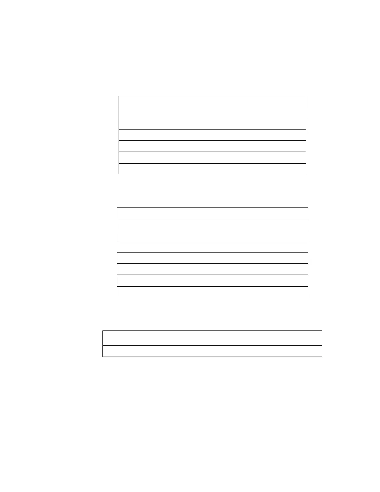
Current Draw Tables for Devices on the Local SLC Branch
The current necessary for local SLC branch operation must be calculated by determining the
current draw of the devices on it. Use Table 2.1 and Table 2.2 to calculate the current draw.
The total local SLC branch current (the sum of the Table Totals from Table 2.1 and Table 2.2) can
not be greater than 20 mA.
Table 2.1 Current Draw of Devices Participating in Degraded Mode on Local SLC
Table 2.2 Current Draw of Devices Not Participating in Degraded Mode on Local SLC
Table 2.3 Total Current Draw of All Devices on Local SLC
Device Qty Current (mA) Total
FSI-751 [ ] X 0.270 =
FSP-751 [ ] X 0.270 =
FSP-751T [ ] X 0.270 =
XP5-M [ ] X 1.651 =
Other Devices [ ] X =
Table Total (Sum of “Total” column) mA
Device Qty Current (mA) Total
ISO-X [ ] X 0.450 =
FCM-1 [ ] X 0.300 =
FRM-1 [ ] X 0.200 =
XP5-C (Relay) [ ] X 0.840 =
XP5-C (NAC) [ ] X 1.481 =
Other Devices [ ] X =
Table Total (Sum of “Total” column) mA
[Table Total from Table 2.1]
+
[Table Total from Table 2.2] =
mA*
*This figure can not be greater than 20 mA.