Installation Circuit Connections
48 XPIQ PN 51013:C 7/01/03
XPIQ-SLI Wiring Style 6
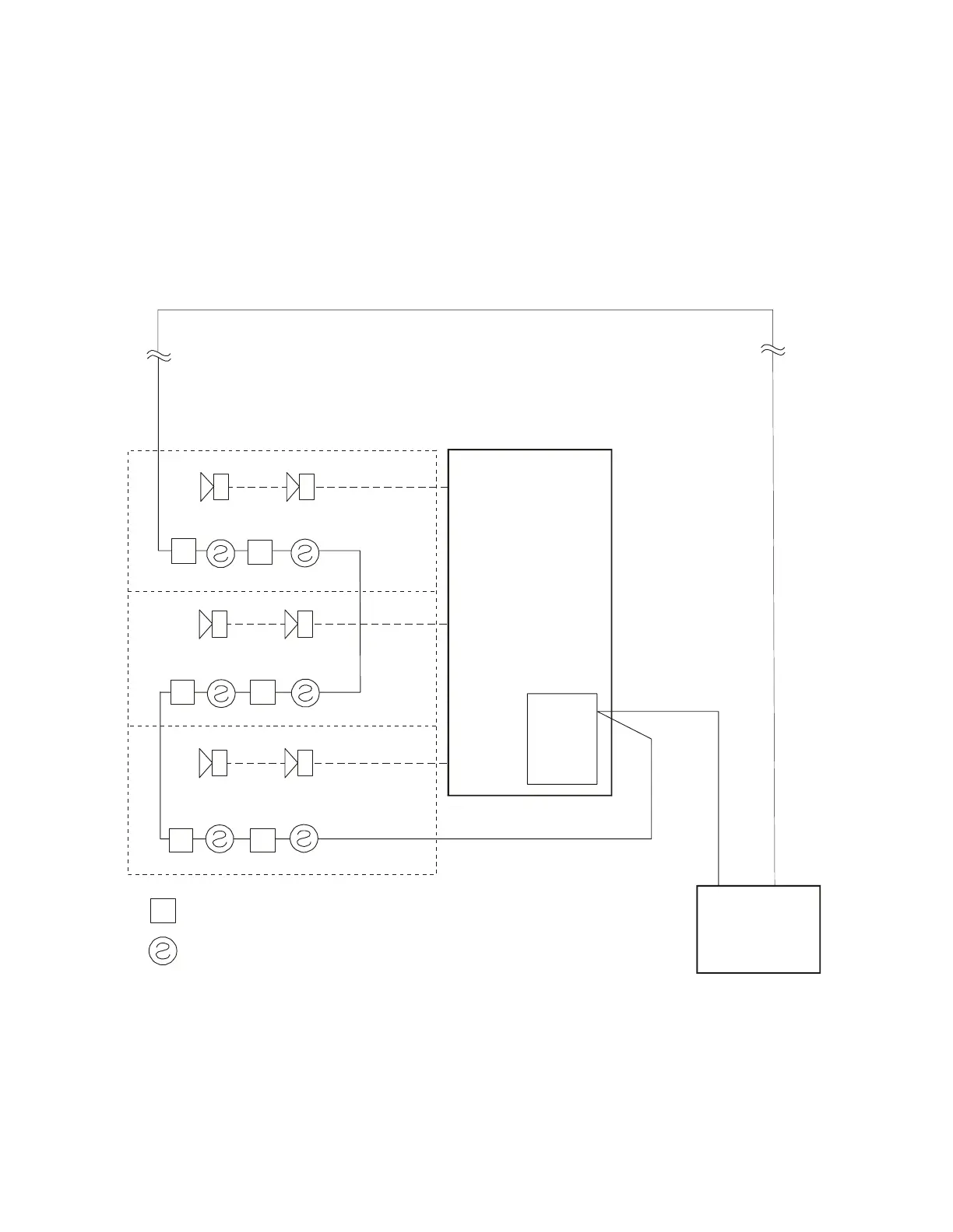
Style 6 wiring is illustrated in Figure 2.23. This wiring configuration allows uninterrupted
communication if a single open exists on the SLC wiring. Style 7 is similar to Style 6 with the
added requirement that isolation modules be installed on both sides of every SLC device, including
the XPIQ-SLI. Each isolator device must be close nippled on each side of the detector/module, or
within 20 feet (6.1 m) of the detector/module in conduit.
M
M
MM
M
M
M
= addressable module
= addressable smoke detector
Figure 2.23 SLC Style 6
FACP
XPIQ-MB
TB1
Zone 3
Zone 2
Zone 1
XPIQ-SLI
SLC
SLC
SLC
XPIQSTY6.CDR