Chapter 2 Installation of OEM7 Family Receiver Cards
OEM7 Installation and Operation User Manual v1 26
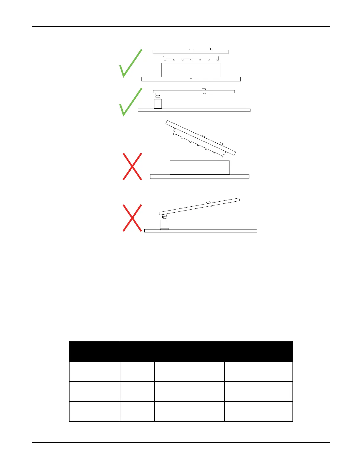
Figure 8: Mounting the High-Density, 60 Pin Connector
OEM7 receivers have an area on the edge of the cards to allow the use of mounting rails. This is
the area of bare copper outside of the keep-out zone. On the OEM719 and OEM7700, this area is
1.75 mm wide. On the OEM729, this area is 2.5mm wide. See Figure 45: OEM719 Mounting Sur-
face on page119, Figure 48: OEM729 Mounting Surfaces on page135 and Figure 51: OEM7700
Mounting Surfaces on page155 for the dimensions of this area.
For most non-demanding applications (e.g. base stations, remote sensing, desktop units and IT
infrastructure), standoffs or bosses are sufficient to provide a secure mounting location.
Using rails to mount the OEM7 receiver improves the thermal and vibration performance of the
receiver. Securing the OEM7 receiver to mounting rails using clamping bars provides the most
secure configuration for aggressive thermal and vibration applications. See Table 1: NovAtel
Mounting Rails below for information about the OEM7 mounting rails available from NovAtel.
Rail Part
Number
Rail
Height
Use as Mounting
Rail for
Use as Clamping
Bar on
01019518 7 mm
OEM719
OEM7700
OEM719
OEM7700
01019519 10 mm
OEM719
OEM7700
OEM719
OEM7700
01019634 12 mm OEM719
OEM719
OEM7700
Table 1: NovAtel Mounting Rails


 To Next Page