4 - 26 en-938821/2
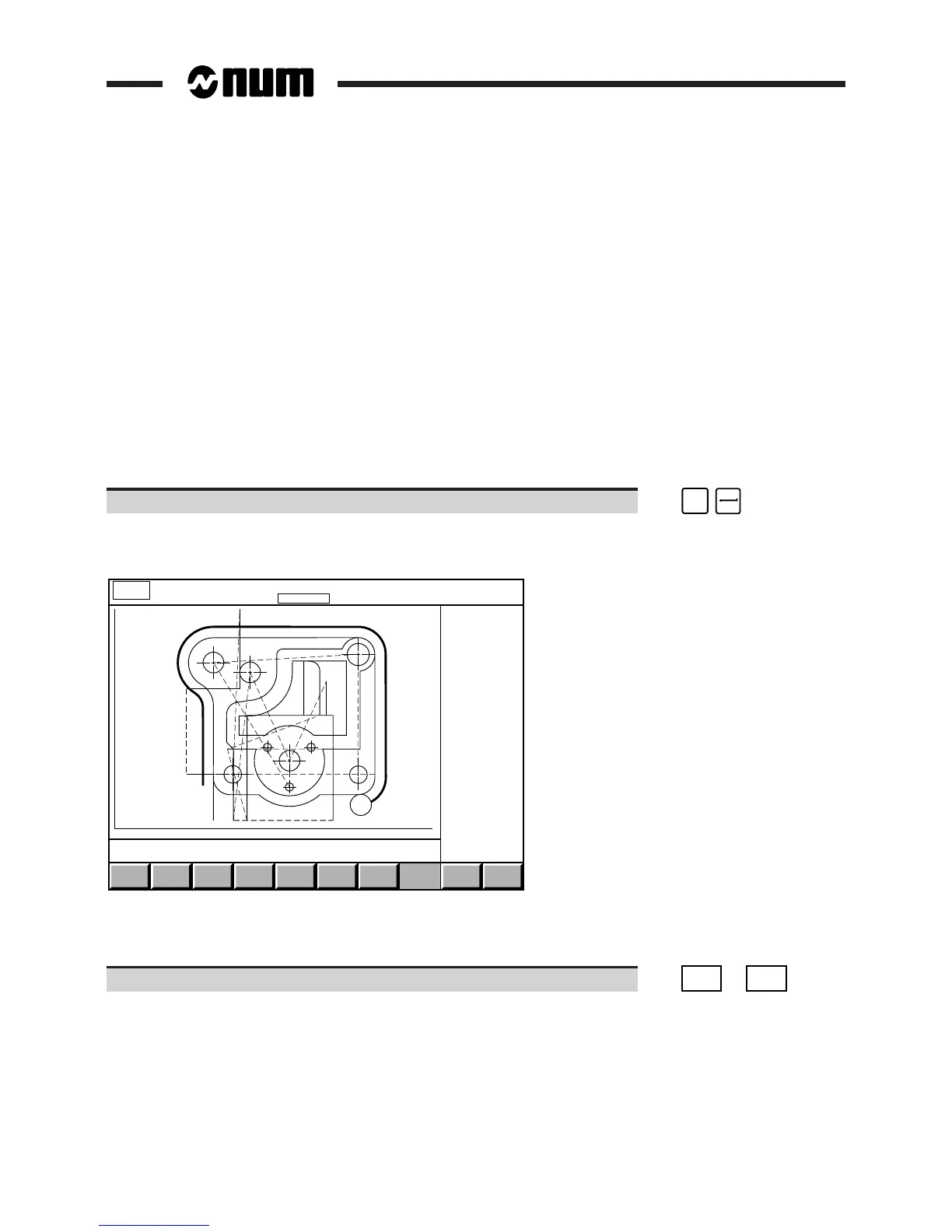
4.6.4 Trace during Cutting
A part cutting phase can be monitored in graphic mode.
The display page shows all the tool movements in real time.
The "trace while cutting" function can be called at any time during or prior to machining.
Requirements
"GRAPHIC - PROGRAMMING" menu displayed (See 4.6).
Active programme selected (See 4.6.1.1) in the graphic display parameters page (programme of one of the groups
in the case of axis multigroup systems).
Part scaled (See 4.6.1).
System already machining or ready to start machining (See 5.4.3.3 to 5.4.3.5).
Actions
Select "TRACE WHILE CUTTING". ☞
#
3
Display of the "trace while cutting" page indicating trace of plane 1.
Display of the programme path:
EXIT
X : -61.202 162.202 Y + 25.4 - 145.0
CLEAR
PLANE
PLANE
1
ERASE
PATH
PROG.
PATH
PLANE
2
Y
X
MACHINE
PATH
AUTO
MODE
START CYCLE
Prog %20
Contour roughing
N90 Y0 EB15
The dialogue window displays the last message and current block.
The tools are represented in the same way as in the simulation function (See 4.6.2).
Select the display plane (if required). ☞
PLANE
1
or
PLANE
2